
Nitrogen Purge and Utility Flow Control for Semiconductor Tools

Nitrogen purge and utility flow on a semiconductor tool
On a semiconductor process or deposition tool, the nitrogen purge and utility positions sit outside the recipe, so they rarely get the scrutiny the qualified gas sticks get. The positions that purge, protect, cool, and carry appear on no qualified parts list, which is why what fills them falls to the tool builder’s own engineering. On a panel drawing they look interchangeable, and they are not: they run from a couple of SCCM to a thousand SLPM, and a few call for a held pressure rather than a flow.
The barrier does not fail loudly when one of them is wrong. It shows up later, in someone else’s yield data, in a fab the tool builder does not visit. Because a purge or utility position is specified by the builder rather than by a fab’s qualified parts list, no wafer-process qualification applies to it, even on a tool that runs production wafers. That absence cuts both ways: it is what makes the position accessible to a standard instrument line, and it means no qualification review stands behind the choice. On a position that then ships to a fab the builder cannot revisit, the specification the builder writes is the only safeguard on the choice.
Challenge
Holding a purge barrier on a non-recipe gas position
Why the purge flow sets the barrier, not the plumbing
A non-recipe purge position is a barrier, not a dose. The chain looks much the same everywhere: bulk nitrogen, isolation and filtration at the gas panel, a regulator, a flow-setting element, then the module being held inert, with a vent at the far end. Ingress works against it continuously, through back-diffusion at openings, permeation, outgassing, and small leaks. The flow-setting element is the one part the tool builder chooses freely, and it decides whether the barrier is a number the tool knows or a valve position someone set at install.
What that flow buys comes down to two relationships, both assuming a reasonably well-mixed volume: how fast the barrier reaches its target, and how well it holds there afterward.
Getting there is dilution. The volume has to be swept several times over, and the number of exchanges is set by how far the purity has to move: clearing an enclosure from air at 20.9 percent oxygen (209,000 ppm) down to an illustrative 100 ppm means diluting the oxygen about 2,090-fold, and the exchanges needed are the natural log of that ratio: ln(2090) ≈ 7.6. Time then follows the flow, because one exchange is the module volume divided by the flow, and the clear needs 7.6 of them. At 500 SLPM a 200 L module turns over once every 200 ÷ 500 = 0.4 minutes, so 7.6 exchanges take 7.6 × 0.4 ≈ 3 minutes. At 150 SLPM each exchange takes 200 ÷ 150 ≈ 1.3 minutes, so the same clear stretches to 7.6 × 1.3 ≈ 10 minutes.
Holding it there is the other half. Once the enclosure is at target, contamination keeps leaking in and the purge keeps sweeping it out, and the level the barrier settles at is where those two balance: to a first approximation, the ingress rate divided by the purge flow. Even treating the ingress as fixed, the same drop from 500 to 150 SLPM that stretched the purge-down is a factor of 500 ÷ 150 ≈ 3.3, so it settles the enclosure at about three times the contamination it was designed to hold. In practice it is worse, because the flow-through purge holds the enclosure a little above ambient, and that slight overpressure is what keeps room air from back-diffusing and leaking in at the openings. A lower flow means less overpressure, so the ingress climbs at the same time the sweep-out falls. A barrier can weaken in both senses at once: slower to reach target, and dirtier once it gets there.
What a drifted purge costs, and where it shows up
None of the ways a purge weakens announce themselves. A filter or line partially clogs. Supply pressure sags when a neighboring tool draws. A needle valve gets bumped during service. A regulator creeps. In every case the flow moves, the plumbing looks identical, and by the arithmetic above the volume either reaches its target far later than designed or holds at a dirtier equilibrium than designed.
Where that surfaces is the expensive part, and rarely at the valve itself. It surfaces as a moisture or oxidation excursion on exposed copper, as an airborne molecular contamination (AMC) signature, as a backside particle count, or as throughput lost while a module waits on an oxygen target it now reaches slowly. Each starts a long investigation, running in a fab the tool builder does not visit, on a tool the builder cannot instrument after the fact. The cost is rarely the gas or the instrument; it is the weeks between the purge moving and anyone connecting the two. A duller cost runs alongside: a needle valve opened generously to be safe overspends nitrogen for the life of the tool.
Specify purge-down in volume exchanges, not in minutes. A time in minutes is only valid at the flow it was measured at. The exchange count survives a change in flow, volume, or purity target, and it makes the flow dependence explicit to whoever sizes the line.
Options
Matching each non-recipe position to an instrument class
The positions below recur across process and deposition tools, and the utility positions on inspection tools. Each is small, and each is usually specified on its own, which is how a tool ends up with several part numbers holding flows and pressures that behave differently. Reading them together shows where one family covers the set, and where a position is a pressure job rather than a flow job.
| Position | What the specification names | Typical duty | What the tool needs to know | Instrument class |
|---|---|---|---|---|
| Equipment and module N2 purgeMost common | A held flow | 200 to 1,000 SLPM, continuous, supply to 250 PSIG | The barrier is flowing, at what rate, and when it is not | Flow controller |
| Tool gas panel outlet | A measured flow | Commonly hundreds of SLPM | What is actually leaving the tool’s own gas panel, per leg | Flow meter |
| Wafer backside back-pressure | A held pressure | Torr region, on a small closed volume | Pressure is held, and at what conditions | Dual-valve pressure controller |
| Chuck cooling gas | A held flow | Low SLPM; commonly helium | Flow is present, on the specified gas | Flow controller |
| Carrier, bubbler, and heater utility flow | A held flow | Single to tens of SLPM | Flow is present and repeatable unit to unit | Flow controller |
| Chuck N2 measurement | A measured flow | Low SLPM | Flow is present; the valve is set elsewhere | Flow meter |
| Load port and front-end purge | A held flow | Emerging, small volumes, cost-sensitive | Flow is present | Compact controller, in trial rather than production |
The class decision comes before range, fitting, or bus: several of these positions are pressure jobs, and getting that backwards is the expensive mistake. Every row otherwise asks the instrument for the same thing, which is what makes one family across a tool’s positions a real option rather than a convenience.
Reading matters as much as control here. A low reading at unchanged supply pressure is a restriction problem; the same reading with supply pressure down is a supply problem. Reporting mass flow, absolute pressure, and temperature together separates them without a second penetration into a crowded panel.
Selection
Consolidating the positions on one measured platform
Every row in the table is buying the same thing. The partial clog, the sagging supply, the bumped valve, and the creeping regulator all move flow while leaving the plumbing unchanged. Where nothing at the position measures the variable the barrier depends on, those are error sources. Measure it and close a loop around it, and the same events become disturbances the position rejects within the valve’s authority and reports when it cannot. The barrier stops being a valve position that was correct at install and becomes a number the tool holds and can flag.
Where purge flow measurement sits in the gas panel
The instrument sits downstream of panel isolation, filtration, and regulation, and upstream of the module it protects. Regulation ahead of it keeps supply inside the instrument’s operating window; filtration keeps panel debris out of a precision flow path. Nothing else about the panel changes. What changes is what leaves the position, because the delivered flow and the conditions it was delivered at now reach the tool’s controls over the bus the tool already uses.
| Family-level capability | What it does for a non-recipe purge position |
|---|---|
| Full-scale options span 0.5 SCCM to 12,000 SLPM | One family covers a chuck line at a couple of SCCM and an equipment purge at 200 to 1,000 SLPM. |
| Mass flow, volumetric flow, absolute pressure, and temperature reported together | Separates a restriction change from a supply change, and logs the conditions the barrier was held at. |
| Wide control turndown | One configuration holds a high purge-down flow and a lower hold flow without a second instrument. As a sizing rule of thumb, keep the hold flow above about 1 percent of the chosen full scale, and size the full scale to the delivery band rather than to an occasional peak purge. |
When the position is wafer backside back-pressure
A wafer backside condition is specified as a held pressure, with practice varying by clamp force and process, commonly landing in the single-digit to low-tens of Torr range. Controlling flow into that volume does not hold pressure in it. A dual-valve pressure controller does, because it can both admit and vent, holding a set pressure on a closed or dead-ended volume without bleeding gas continuously. Settle which variable the specification names first, because that decides the instrument class before anything else does.
A person is present to read the position. Where the flow is allowed to be a manual setting and someone reads it, a needle valve and a variable-area meter are the right answer and always were. The case for an instrument rests on the position being unattended for years, not on the rotameter being imprecise.
The flow is genuinely fixed for the life of the tool. Where the flow does not change and the supply is tightly regulated, a fixed orifice costs less, draws no power, and has nothing in it to drift. It annunciates nothing, so the choice trades lower cost against having no feedback from the position.
The position is on the qualified parts list or doses the recipe. A gas stick is qualified as a unit, so changing the instrument means requalification. Use the process MFC the qualification names; it is out of scope here.
The position specifies ultra-high-purity materials. Where a leading-edge fab has written a wetted-materials standard calling for electropolished surfaces and all-metal seals, a standard utility instrument does not meet it. Alicat’s oxygen-cleaned preparation and corrosion-resistant build are a cleaning process and a materials option; neither is a purity certification, and neither should be represented to a fab as one.
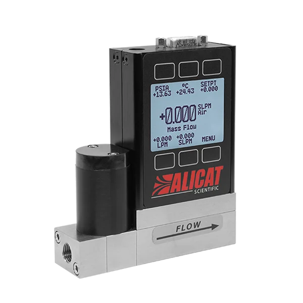
MC-Series Mass Flow Controllers
Equipment, module, gas panel, and carrier purge duty
Laminar differential pressure flow controllers for the positions that hold an inert barrier, cool a chuck, or carry a utility gas. Equipment and panel purges in this class typically run 200 to 1,000 SLPM continuously.
- 98 to 130 preloaded gas calibrations (Gas Select); change the active gas without recalibration
- Accuracy is range-dependent: ±0.6% of reading or ±0.1% of full scale (whichever is greater) in the mid-flow ranges, and ±0.8% of reading with ±0.2% of full scale in the low and high-flow ranges, which include the hundreds-of-SLPM equipment-purge band; a higher-accuracy option is offered in each range
- Flow repeatability ±(0.1% of reading + 0.02% of full scale) in the mid ranges, and ±(0.2% of reading + 0.02% of full scale) in the low and high-flow ranges, so every unit of a configuration behaves the same
- Laminar DP sensing with temperature and pressure correction, factory-calibrated on air and translated to the working gas from its resident real-gas property models
- High-flow, low-pressure-drop variant for continuous equipment and panel purge duty
- Analog, serial (RS-232 or RS-485, running Alicat’s native ASCII protocol or Modbus RTU), and industrial network options such as EtherCAT and EtherNet/IP; compression or metal face-seal process connections
- NIST-traceable calibration certificate with every unit, made to order with current lead time confirmed at quote
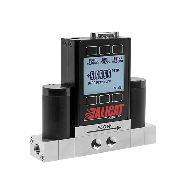
PCD-Series Pressure Controllers
Wafer backside back-pressure and small enclosed volumes
For non-recipe positions whose specification names a pressure rather than a flow.
- Controls absolute, gauge, or differential pressure, with torr-region absolute ranges for backside and enclosed-volume duty
- Dual valves admit and vent, holding a set pressure on a closed or dead-ended volume without bleeding continuously
- Steady control across a wide turndown, holding low setpoints without a second instrument
- Pressure reported to the tool alongside the conditions it was held at
- Analog, serial (RS-232 or RS-485, running Alicat’s native ASCII protocol or Modbus RTU), and industrial network options such as EtherCAT and EtherNet/IP
- NIST-traceable calibration certificate with every unit
Related families: the M-Series mass flow meters where the position only needs the flow measured, such as a gas panel outlet or a chuck nitrogen line; vacuum-service controllers where a position runs sub-atmospheric; and the compact IMC-Series, currently being trialed for the simplest load port and front-end positions rather than shipped in a production program. Talk to an engineer to confirm fit and select a configuration.
Configure the right instrument for your purge positions.
Send the position list: gas, flow or pressure range, supply pressure at the panel, fitting, connector, and the bus the tool runs. What comes back is a family and configuration recommendation for each position, and where one configuration can cover several.
Outcomes
What holding these positions changes
Measured and controlled, a purge position is no longer a setting trusted since install; it is a value the tool holds, logs, and can flag. Those same failures no longer wait to surface as someone else’s yield excursion; they show up at the position, as a flow that moved and an alarm that fired, before the module they protect is compromised. Reporting mass flow, absolute pressure, and temperature together lets the tool separate a restriction from a supply problem out of its own logs rather than from a service visit.
Reading the positions together, rather than one part number at a time, is what lets a single family cover a chuck line at a couple of SCCM and an equipment purge at a thousand SLPM. And a purge that is measured can be right-sized: the standing nitrogen cost of a valve opened generously to be safe is real over the service life of a tool, and it is only recoverable once someone can see what the position actually draws.
Value gained
- A barrier the tool can prove – the purge becomes a measured, logged number with an alarm band, not a valve position assumed correct since install.
- Restriction told apart from supply – mass flow, absolute pressure, and temperature on the same bus separate a clogging filter from a sagging supply without a second panel penetration.
- One family across the positions – full scales from 0.5 SCCM to 12,000 SLPM cover chuck, carrier, panel, and equipment purge duty from a single instrument family.
- Right-sized nitrogen – a measured purge can be sized to what the barrier needs, recovering the standing gas cost of an over-opened purge valve.
- Flow or pressure, matched to the spec – a flow controller where the position names a flow, a dual-valve pressure controller where it names a pressure such as wafer backside.
Field deployment notes
Engineering considerations
- Supply pressure above the standard operating window
- The standard MC-Series operating window is 11.5 to 160 PSIA. Equipment purge supply at a panel commonly runs well above that, and 250 PSIG inlets are routine on high-flow purge duty. Either regulate down ahead of the instrument, which most panels already do, or specify the high-pressure variant of the family, which operates to 320 PSIA. This is a placement decision on the panel drawing, so it is cheaper to settle before the panel is laid out than after.
- Available pressure drop at high purge flow
- A high-flow purge line often has little pressure to spare between the regulator and the module, and any flow element consumes some of it. Confirm the available differential before fixing the full-scale range, because too little differential shows up as an instrument that cannot reach setpoint at the top of its range. Where the margin is thin, the low-pressure-drop variant exists for this case. See what pressure drop means for instrument selection.
- Alarm band policy across purge-down and hold
- One low-flow alarm band rarely suits both regimes. During purge-down the flow sits at its commanded maximum and a tight band around it is meaningful. During hold the flow may legitimately sit much lower. Decide whether the tool latches a purge alarm or treats it as advisory, and whether a purge-down running long should block the next step. That decision belongs to the tool’s controls, not to the instrument.
- Oxygen-cleaned preparation and corrosion-resistant materials
- Both exist as build options and both are routinely misread. An oxygen-cleaned preparation is a cleaning process applied to the flow path. A corrosion-resistant build is a wetted-materials choice. Neither is a purity certification, neither makes the instrument a clean or ultra-high-purity device, and neither should be represented to a fab as one.
- Recalibration on a fleet the builder does not visit
- Alicat’s stated interval is annual. On a tool population sitting in fabs the builder does not service, that interval is a conversation to have with the fab rather than an assumption to carry. Decide at design time whether the purge instrument is field-replaceable, a return-for-service item, or one the fab’s own calibration program picks up, because that decision drives the panel layout and the spares list.
Frequently asked questions
Is a rotameter good enough for a nitrogen purge?
A rotameter is adequate where a person is present to read it and the purge flow is allowed to be a manual setting. It is not adequate on a shipped tool, because it publishes nothing to the tool’s controls and gives no warning when the flow moves, which is the failure mode a purge position actually has.
Does a purge mass flow controller need SEMI qualification?
No. A non-recipe purge or utility position is specified by the tool builder’s own engineering rather than by a fab’s qualified parts list, so it carries no wafer-process qualification requirement, even on a tool that runs production wafers. SEMI publishes guides and reference documents; there is no instrument certification a purge MFC passes. The tool itself still meets SEMI equipment guidelines such as S2, but that sits with the tool builder, separate from qualifying the instrument for a recipe.
How much nitrogen does a continuous tool purge use?
Enough that it is a standing operating cost rather than a rounding error. Equipment and gas panel purges running in the hundreds of SLPM run continuously for the service life of the tool, and a valve set with generous margin overspends for that entire period. Measuring the position is what makes right-sizing possible.
What is the difference between a recipe MFC and a purge MFC?
A recipe MFC doses chemistry that becomes film or etch and sits on a qualified parts list, so both its accuracy and its pedigree are specified by the fab. A purge instrument holds a protective barrier flow, is selected by the tool builder, and is specified for stability and for the ability to prove the barrier is present.