
Measuring and Controlling Purified Nitrogen in a Semiconductor Fab Gas System

Purified nitrogen in a semiconductor fab
The high-flow nitrogen that runs a fab is metered by the people who build its gas systems. Panel and system builders assemble the purified-nitrogen delivery and distribution that feeds inspection, metrology, and deposition tools, and they order the flow instruments in those assemblies helium-leak-checked and oxygen-cleaned. Alicat meters and controllers already run in those positions, commonly at 250 to 500 standard litres per minute. One capability of that instrument rarely reaches the datasheet: it turns a point-of-use purifier’s service life from a commissioning-day assumption into a measured number.
House nitrogen arrives at the fab already at five nines (99.999% pure), and the last two orders of magnitude of purity get bought back at a consumable bed near the point of use. That bed is sized against an assumed flow, and the assumption is rarely revisited once the skid is commissioned. Several instruments can sit on either side of it, all adequate on the datasheet, each hiding a different cost that shows up months later. The gas gives no early warning; it stays clean until the analyzer says otherwise, and by then the maintenance plan is already wrong.
Ultra-high-purity (UHP) nitrogen is the highest-volume gas in a fab and it is not a recipe gas: it purges, blankets, carries, and fills, continuously, across the tool floor, the load ports, and the lab benches. The bulk source already delivers roughly five nines, so everything difficult happens in the last two orders of magnitude. The fab does not simply buy cleaner nitrogen because purity is not a property the gas carries with it. It is a property of the gas at the point of connection, and the piping degrades it: tubing outgasses moisture, fittings permit permeation, every joint is a candidate for oxygen ingress. So the architecture pushes purification downstream, where a point-of-use or area purifier polishes 5N house nitrogen to sub-ppb immediately before the manifold feeding the tools.
That solves the purity problem and creates another. A purifier is a consumable bed, a heated getter or ambient-temperature fill depending on the impurities removed, holding finite capacity for the oxygen, moisture, carbon monoxide, and carbon dioxide it chemisorbs. Vendors size it against a nominal flow and a target interval, typically one or two years at nominal flow. Capacity is spent in proportion to the gas passed, not by the calendar.
Challenge
The purifier’s service life is a budget you cannot see
One caveat first. Often this does not bite: the ITRS Yield Enhancement chapter (2009) records that where point-of-connection purity is already adequate, the prevailing approach is to treat the purifier as insurance, the challenge to it is minimal, and long lifetimes can normally be expected. On a bed generously sized against a clean 5N inlet that is the right read and none of what follows applies. It stops being right in two cases: a bed sized to a budget rather than a margin, or a manifold whose demand has drifted above the commissioning sheet. Those are the legs worth metering.
For those legs, overflowing a purifier does not necessarily dirty the gas. A point-of-use purifier’s table carries two flow numbers per model. NuPure’s PF Series lists an average flow for a one-year lifetime alongside a separate, much higher maximum flow: for the 1000 PF vessel, 10 slpm average against 50 slpm maximum. This is how point-of-use purifiers are rated across the category: the recommended flow targets a one-year life between regeneration or replacement, and actual lifetime follows actual flow.
A bed run at maximum rather than nominal flow stays within its published limits, produces rated purity, and passes every check the fab makes. The two figures differ by roughly fivefold, so capacity is spent about five times faster than the sizing assumed: a vessel specified for a year reaches the end of it nearer a quarter of the way in, and breakthrough (when the spent bed starts passing impurities) shows up months ahead of plan.
It cannot be caught by inspection either. Remaining capacity is not observable for most impurities: saturation can be measured where a bed removes moisture, but for many contaminants it cannot reliably be determined, so practice is to regenerate or replace at the known duty cycle rather than await degradation. That only works if the duty cycle is real, and a commissioning-day assumption left untracked for a year is not.
Size and schedule against nominal flow, not maximum. The maximum rating says what a bed can pass without damage; the nominal rating says what it can pass and still reach the interval you planned. Published point-of-use tables commonly separate the two by several fold, and that gap is the whole service-life budget.
Options
What can measure the delivered flow
There are two positions and two decisions: an inlet device holding throughput at the bed’s nominal design flow, and a delivery-side device reporting what the manifold passes. Many skids populate only the delivery side. What the delivery-side instrument has to establish is how much of the bed’s budget is left, and the bed gives no direct reading of it. Flow can be read, and because capacity is spent in proportion to the gas passed, a running sum of flow stands in for the capacity consumed. That is the job: keep an honest running total across a year of varying demand, not just the rate at any one moment.
Four measurement technologies could fill either position, and two fall away against that requirement. A variable-area meter, or rotameter, reads the instantaneous rate off a float and keeps no running sum, so it fits only a leg that runs one fixed rate forever with nobody tracking consumption. An ultrasonic meter is standard on the house main, where the bore and straight run exist to develop a profile; a skid offers neither. That leaves thermal and laminar differential pressure, comparable on a single pure gas and making similar demands on inlet pressure.
Between the two, interpretability decides it. Multivariable output makes the reading interpretable: flow alone says a leg changed, flow with local absolute pressure says whether demand moved or something upstream is failing. On that basis laminar differential pressure is the best fit here, though the balance reverses where the gas is not reliably particle-free. Even so, the totalizer is not sufficient on its own: it turns a scheduling assumption into a measurement, but the analyzers still decide whether the gas is clean.
The meter sits ahead of any particle filter. Purity, the five-nines figure, is a chemical spec, oxygen and moisture in ppb; it says nothing about particles, which the distribution piping and valves shed regardless of how clean the source gas is. The meter measures across a stack of laminar flow elements, thin plates that split the gas into many fine parallel passages; that geometry is what makes the measurement possible, and it is also what particles clog. Downstream of the purifier the gas has passed the purifier’s filter, so the delivery-side meter is protected; ahead of that filter, confirm upstream filtration or use a thermal instrument, which has no fine passages to protect and is more forgiving.
The leg runs at one rate and nobody needs the number. If demand is a single fixed setpoint, the bed is oversized against it, and no one schedules against duty cycle, a rotameter and a regulator are the correct answer. Where there is nothing to totalize, the case does not apply.
The instrument is already written into the system spec. A purification and distribution system is usually built to the end user’s design or a fab’s approved-vendor list, so the flow instrument is often fixed before any bench comparison. Where the spec is already set, the position is won by getting onto it, not by out-measuring the incumbent.
Selection
Totalize the delivered flow with a laminar-DP meter
The instrument that answers this is a laminar differential pressure meter on the delivery side, keeping a running total of what the manifold passes. Read against the bed’s rated capacity, that total is what the service interval is scheduled against.
The arithmetic is quick. Take the line from earlier: a vessel rated 10 slpm average for a one-year life, 50 slpm maximum. A year at that average is roughly 5.3 million standard litres. That number, not the calendar, is the bed’s budget, and the totalizer is the only in-line reading counting against it. Run the same vessel at 30 slpm, inside its published maximum and still delivering rated purity, and the budget is gone in about four months. The gas itself gives no sign; the totalizer does, on day one rather than at breakthrough.
The instantaneous reading is the less interesting half: a leg at 30 slpm looks fine on any meter, and the fact that it has spent a year’s budget by month four is something only a running total reveals.
That budget is an approximate figure, not a guaranteed volume: it is the capacity implied by the vendor’s nominal-times-life rating, a bed worked near its maximum reaches breakthrough at somewhat less total throughput, and the number assumes the inlet purity the bed was rated against. Read the running total as whether a leg is ahead of or behind its planned consumption, rather than a countdown to an exact litre. Confirm the rated capacity with the vendor before running a bed deliberately above its nominal flow.
This also changes what matters on the datasheet. The headline accuracy percentage, the percentage-of-reading figure usually quoted, counts for less here than it looks: a totalizer running 1% low shifts the replacement date by about four days over a one-year interval, and 5% low by about eighteen, both trivial next to the months that a leg quietly running above its assumed rate would move it. Sizing is the stronger lever, because sizing is what decides how much the full-scale term of that same spec costs. Accuracy is quoted as a percentage of reading plus a percentage of full scale, and the full-scale part is a fixed error that grows as a share of the reading as the reading falls, so an oversized meter is where it bites: a 500 SLPM meter on a leg that draws 5 SLPM is off by roughly a fifth of its reading, and a year of that adds up to weeks of schedule error. Match the meter’s full scale to the leg’s real duty, not its peak, and that term stays small.
| Capability | Published figure | What it does for this skid |
|---|---|---|
| Totalizer uncertainty | ± 0.1% of reading additional | Makes the accumulated volume a number the schedule can be built on. |
| Multivariable output from one body | mass flow, volumetric flow, absolute P, T | Tells a demand change from an upstream problem, from one tap into the line rather than a flow meter plus a separate pressure gauge. |
| Calibration traceability | NIST-traceable certificate | The delivery reading is the record of what the manifold delivered, so it has to trace to a national standard. |
| Control range, MCR-Series controller | 0.2–100% of FS (500:1 turndown) | Holds the bed at nominal design flow. Its control range is narrower than the meter’s measurement range, so plan the inlet accordingly. |
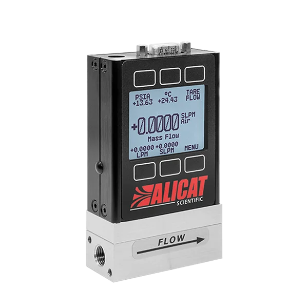
M-Series Mass Flow Meters
Delivery-side verification, downstream of the purifier
An in-line laminar differential pressure meter for the clean side of the purifier, reporting what each leg passes and keeping the cumulative total across a service interval.
- Totalizer carrying ± 0.1% of reading additional uncertainty
- Mass flow, volumetric flow, absolute pressure and temperature from one manifold penetration
- ± 0.8% of reading + 0.2% of full scale standard; ± 0.4% of reading + 0.2% of full scale high-accuracy option at or below 500 SLPM
- Analog; serial (RS-232 or RS-485, running Alicat’s native ASCII protocol or Modbus RTU); and industrial network options such as EtherCAT and EtherNet/IP, so the totalized volume reaches the maintenance system rather than a local display
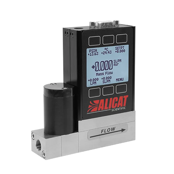
MCR-Series Mass Flow Controllers
Inlet flow control, upstream of the purifier
The high-flow companion to the meter, on the skids that populate the inlet side: it holds the bed at its nominal design flow so the service-life budget is spent at the rate the sizing assumed, not at whatever the manifold happens to draw.
- Holds throughput at the purifier’s nominal design flow, so the interval is scheduled against a rate that is enforced rather than assumed
- 0.2 to 100% of full scale control range (500:1 turndown); plan inlet range against this, narrower than the meter’s 10,000:1 measurement turndown
- Onboard absolute pressure and temperature from the same body, so the inlet pressure the bed actually sees is a reported value, not an inference
Where inlet pressure is tightly constrained, ask about the low-pressure-drop Whisper-series controller. Talk to an engineer to confirm fit.
Configure the right instrument for your purification skid.
Send the purifier’s nominal and maximum rated flow, the leg’s real demand profile rather than its peak, the fitting and cleaning preparation your specification calls for, and the interface your controls read. Back comes a full-scale recommendation sized to that duty, with the drop at your real operating point and current lead time.
Outcomes
What the measurement changes
Metering the delivered flow changes how the skid is maintained. Replacement stops being a calendar entry or a commissioning-day guess and becomes a decision driven by measured throughput: the totalized volume is read against the bed’s rated capacity, and the bed is changed when the count reaches it, whether that lands at twelve months or four. A leg that quietly drifts above its planned rate surfaces on day one of the drift rather than at breakthrough months later, so a contamination event that would otherwise arrive unannounced becomes a scheduled swap.
The same instrument does double duty. Sitting on the clean side of the purifier, it is a NIST-traceable record of what actually reached the tools, not an inference from what entered the bed. And because it reports absolute pressure and temperature alongside flow from a single tap, a change on a leg reads as a demand shift or an upstream problem without adding a second instrument.
Value gained
- Scheduling on real consumption – replacement is driven by measured throughput against the bed’s capacity, not a commissioning-day assumption or the calendar.
- Early warning – a leg drifting above its planned rate shows up on day one, not at breakthrough months later.
- Delivery verification – a clean-side, NIST-traceable record of what actually reached the manifold.
- Diagnosis from one body – flow, absolute pressure, and temperature from a single tap separate a demand change from an upstream problem.
- One platform across the skid – the M-Series meter on the delivery side and the MCR-Series controller on the inlet share the same measurement method and interface.
Field deployment notes
Engineering considerations
- Reference conditions have to match before the flow numbers can be compared
- Purifier vendors rate capacity in slpm without always stating the reference temperature and pressure behind it, and the common references differ: 0 °C and 1 atm against 25 °C and 1 atm is roughly an 8% difference in the same physical flow. Alicat instruments default to 25 °C and 1 atm for STP and 0 °C and 1 atm for NTP, and both are user-configurable. Set the instrument’s reference to the one the purifier’s rating uses before comparing the reading to the bed’s nominal flow, or the service-life budget is being tracked against a number that is a few percent wrong from the first day.
- An idle leg is not a safe leg
- The flow-related failure runs in both directions, and the low-flow direction is the one that surprises people. The ITRS Yield Enhancement chapter (2009) notes that when flow in a distribution system is decreased, moisture contamination from outgassing tends to increase: with less gas moving through the line, the pipe’s own outgassing makes up a larger share of what reaches the point of use, so a leg that has gone quiet is not necessarily resting. The meter does not see that moisture; the analyzers do. What the delivery-side reading adds is the trigger. A leg whose flow has dropped well below its commissioned demand gets flagged for someone to check, rather than sitting unnoticed until the analyzer catches it downstream.
- The totalizer has to survive the service cycle deliberately
- The value of the accumulated total comes from its continuity across a year, and the instrument’s power-up behavior is a setting rather than a given. By default the totalizer starts from zero on power-up; enabling the Save Totalizer function makes the device store the running total at regular intervals and restore it after a power cycle. Decide before commissioning which you want: enable saving so the total carries across service stops and unplanned power interruptions, or leave the default and read, log, and reset the total at each service stop. Either is workable; what fails is running the default while assuming continuity, so that a power cycle nobody recorded silently truncates the integral the schedule is built on. Even with saving enabled the total is written periodically rather than continuously, so an outage drops only the flow since the last save, not the whole record.
- The laminar flow elements need upstream particulate protection
- The meter measures across a stack of laminar flow elements, thin plates that form many narrow parallel passages, and that geometry is what makes the differential pressure measurement possible. It is also what makes it vulnerable to particulate. On the inlet side the gas is 5N house nitrogen that has travelled a distribution network, so it is not necessarily clean of particles even though it is nearly clean of gaseous impurities. Confirm filtration upstream of any inlet-side instrument.
- Rolamite valve orientation constrains the inlet-side layout
- The high-flow controllers in this family use a Rolamite valve, which must be mounted upright. On a densely packed skid this is a layout constraint rather than a detail, and it is easier to accommodate on the drawing than after the frame is welded. The meters carry no such orientation requirement.
- The pressure budget closes across the whole skid, not per component
- The purifier has a drop, the instrument has a drop, and the manifold’s regulation has to deliver the leg’s required pressure after both. The instrument’s published drop is stated at full scale venting air to atmosphere, so the number at an actual operating point below full scale on nitrogen will differ. Ask for the figure at the real operating point rather than reading the table value as the answer. Because the instrument reads absolute pressure at its own position, the pressure the manifold actually delivers is one of the values it reports, so the budget can be verified in service rather than only calculated on the drawing. See what pressure drop means for instrument selection.
Frequently asked questions
What flow rate does a nitrogen purifier need?
A purifier has two different flow ratings and they do different jobs: a nominal or average flow, which is the rate the bed was sized against to reach its target service life, and a maximum flow, which is the most it can pass without damage. Published point-of-use tables commonly separate the two by several fold. Size and schedule against the nominal figure.
Running between nominal and maximum is not a fault condition and does not by itself put the outlet gas out of specification. It consumes the bed’s finite capacity proportionally faster, which shortens the interval to regeneration or replacement.
Does a mass flow meter on a fab nitrogen line need to be SEMI qualified?
Not in a purification and distribution position. Qualified parts lists are maintained by tool makers for the recipe-tier gas sticks inside their process tools, where the instrument is part of a qualified process. A purifier skid feeding a distribution manifold is a utility position, so instrument selection there is governed by the integrator’s engineering specification rather than by a tool’s qualification.
SEMI publishes guides that shape how these systems are built and verified, including F22 for bulk and specialty gas distribution architecture. They are guides and reference documents, not a certification an instrument passes.
Can one instrument do both inlet control and delivery verification?
No. The two jobs are on opposite sides of the purifier, and one instrument cannot be in both places. Inlet control needs a controller with a valve upstream of the bed; delivery verification needs a meter downstream of it, so that what it reports is post-purification gas. A skid that wants both needs one of each, and many run only the delivery-side meter.
Where budget forces a single instrument, keep the delivery-side meter. It sits on the clean side of the purifier, so its laminar elements are protected from particulate, and being downstream it reads what actually reaches the manifold rather than what enters the bed.
Will a flow meter detect a leak in a UHP nitrogen distribution system?
It will flag a gross change in what a leg is passing, which is a useful integrity indicator, but it is not a leak detection method and should not be specified as one. A flow change tells you something moved; distinguishing a leak from a demand change or a blockage takes the local pressure context. Because these meters read absolute pressure from the same body, that context arrives with the flow reading rather than from a separate gauge, which sharpens the diagnosis without making the meter a leak detector.
The method the industry codified for distribution integrity is non-invasive oxygen ingress measurement, described in SEMI F35. That standard now carries inactive status, though SEMI states inactive standards remain valid for use, and the method is still how ingress is verified in practice. Flow monitoring complements it rather than replacing it.