
Flow and Pressure Control for Semiconductor Metrology and Inspection Tools

Purge and pressure control inside a metrology tool
A metrology or inspection tool is built to resolve small differences, and several of the gas positions inside it sit closer to the measurement than they look. In a short-wavelength optical tool, the measurement runs at wavelengths that ordinary air absorbs, so the tool flows nitrogen across its light path to push the oxygen out of the way, down to a few parts per million, where the beam reaches the detector clean. That purge is one of several small gas positions inside one tool, and the same pattern recurs across optical, electron-beam, and probe-based instruments: a flow over an optic, an absolute pressure held in a chamber, a carrier feeding an integrated analyzer. Each runs on its own gas, and each is usually written into the design the way plumbing is: deliver this much, keep it clean.
But that purge is part of the measurement, not a utility feeding it. Let it run five percent below its setpoint and roughly five percent more oxygen sits in the beam path, and the reading moves with it. The shift is small, and it does not average away: it is the condition the measurement runs under, moving underneath the measurement. It seldom shows on the bench, and turns up months later as a tool that no longer agrees with the data it qualified against, in a fab the builder does not control.
Challenge
Holding the purge and chamber conditions a measurement depends on
Two facts force the architecture. The measurement needs a gas environment that is not the ambient one: short-wavelength optical, vacuum-ultraviolet, and extreme-ultraviolet measurements are absorbed by the air they travel through, and depending on wavelength the tool answers that either by evacuating the path or by holding it under a controlled low-absorption atmosphere such as nitrogen, clean dry air, or helium. An electron column or environmental chamber needs a specific absolute pressure instead, because that pressure sets the physics the measurement runs under. And the enclosure holding that environment cannot be sealed and filled once, because it carries beam apertures and wafer-handling openings and its surfaces outgas. The environment has to be maintained continuously by flow, which puts the flow device inside the measurement chain rather than beside it. One tool often carries several such zones: an optical thin-film metrology system may purge its light source, focus housing, illumination and collection optics, main housing, and detector housing separately (US Patent 7,755,764 B2, 2010).
How that flow is arranged carries a consequence a utility specification does not anticipate. The purge runs as a flow-through: inert gas passes through the enclosure continuously and leaves through a vent, and the box is held slightly above ambient pressure so leakage is always outward and room air cannot diffuse back in through the apertures. The through-flow does the diluting; the slight positive pressure keeps air from returning. The residual is roughly the in-leak divided by the flow, so flushing harder both drives it down and blunts what a flow error does to it. But the flow cannot run arbitrarily high: purge gas costs money, helium especially, and a strong flow over the optics brings its own vibration and thermal gradients. So it settles at a bounded target flow, one the same purge-control design steps up for vacuum-ultraviolet measurements and back down for UV-visible ones. At that operating point the in-leak term is a live part of the contamination budget, and a wander in the flow moves the residual, and with it the reading at the detector.
What instability costs once the fleet is installed
A purge or pressure wander does not stay in the gas system. It enters the reading as baseline drift, which sits underneath the tool’s repeatability and cannot be averaged away, because it is not noise. The distinction between accuracy and repeatability is the one that matters. A fixed accuracy offset is absorbed when the tool builder characterizes the system as built. A repeatability or drift term is not: it moves between runs, between power cycles, and between one instrument and the next on the production line, and nothing at tool level is positioned to catch it.
It costs the OEM again after shipment. The instrument is calibrated on a bench, boxed, and installed in a fab the tool builder does not control, and a drift in the gas control does not arrive looking like a gas fault. It looks like a tool that no longer matches the data it qualified against, and the first hours of diagnosis go to the optics or the detector. The correction is a service visit to the fab, and across a fleet it is that same visit many times over. Reproducible configuration and stability over the tool’s field life are reliability requirements here.
Size a purge controller so the tool’s normal operating flow sits near the middle of its range, not at the bottom. Repeatability carries a percent-of-full-scale term alongside a percent-of-reading term, and the full-scale term dominates once a position runs at a few percent of range. Choosing a full scale to leave headroom for a flow the tool will never use puts the position in exactly that region.
Options
Specifying each gas position in the tool
The positions below recur across optical, electron-beam, and probe-based tools. Each is small, and each is usually specified on its own, which is how a tool ends up with four part numbers holding four flows that behave differently. Reading them together shows where one family covers the set and where a position needs something else.
| Position in the tool | What it has to hold | What it has to report | What usually decides the pick |
|---|---|---|---|
| Optic and detector purge | A low flow, steadily and continuously, over a beam path or a detector window. | Flow, and the pressure it is delivering against. | Repeatability at the low end of the range, and how much inlet pressure the purge feed can spare. |
| Measurement chamber backfill | Either a flow into a pumped volume, or the chamber’s absolute pressure directly. | Flow and absolute pressure, referenced to vacuum. | Whether the tool controls pressure as the variable, or controls flow and lets pressure settle against the pumps. |
| Sample and carrier flow to an integrated analyzer | A stable carrier or sample flow, held across a run. | Flow and temperature. | Run-to-run repeatability, because the analyzer’s own calibration assumes the carrier flow did not move. |
| Probe and characterization environment | A conditioned gas environment around the device under test. | Flow and absolute pressure. | How many gases the position runs, and how often they change. |
| Field and lab verification | Nothing. This position measures rather than controls. | Traceable flow, on battery, wherever the tool is installed. | Calibration traceability and portability, not control performance. |
Several instrument classes hold these conditions competently. A fixed restriction on a regulated supply is right for a purge that keeps particulate off a housing at one condition; a thermal mass flow controller holds these flows well, and on the inert gases these tools run its accuracy matches the alternatives here; a pressure held upstream of a characterized orifice is fast and proven where the gas never changes. What separates them at design-in is not which controls better, but how much of the required reporting a single instrument covers, and how many part numbers the tool carries as a result.
Selection
Consolidate onto measured, self-reporting instruments
Most of these positions control a flow: the optic purge, the chamber backfill, the sample carrier. Hold them with a measured flow controller and the reporting problem answers itself. A laminar differential-pressure controller derives flow from an absolute pressure and a temperature it measures inside its own body, and it reports all three as outputs, so the conditions behind each reading are logged without a second device. That is what makes a later drift attributable: when the flow held while the supply moved, or the flow moved while the supply held, the tool reads the difference from its own logs.
One measured flow controller also collapses the part count across those positions. Gas properties come from an on-board library evaluated against the instrument’s own measured pressure and temperature, so changing the active gas is a direct selection, and the optic purge and the sample carrier land on a single configuration that differs only in full-scale range and the gas selected. The controller’s published repeatability is small against the drift budgets these tools work to, so the gas control is no longer the largest error term in the measurement. The measurement chamber joins those flow positions whenever its gas is run as a backfill against the pumps; what sets it apart is that its pressure can be the measurement condition itself, and then it is held differently.
Holding the measurement chamber’s pressure
When the chamber’s pressure is the measurement condition itself, it is the quantity that has to be held to spec, referenced to vacuum rather than to the local atmosphere, which moves with the weather and the fab’s air handling. Variable-pressure and environmental electron microscope chambers run orders of magnitude below atmosphere, with environmental modes commonly reaching roughly 1 to 20 Torr and up to about 50 Torr on some instruments. That pressure governs how much of the beam scatters out of the focused probe before it reaches the sample, so it trades charge neutralization against resolution, and the tool has to record where on that trade each image was taken.
It can be held two ways, both with a measured instrument. On a continuously pumped chamber, a flow controller admits gas against the pumps and the pressure settles where inlet flow balances pumping speed; the same flow controller can control on its own absolute pressure rather than on flow, so it holds the pressure directly while staying the instrument already used across the tool’s flow positions. On a closed or dead-ended chamber where the gas has no natural exhaust, or where the pressure has to be held more tightly than a flow settling against the pumps can manage, a dual-valve pressure controller belongs there instead: it admits and vents to hold the setpoint directly and without a continuous bleed, reaches into the Torr region, and references the pressure to vacuum. Its accuracy is published on full scale rather than on reading, so the full-scale range is chosen to sit near the operating pressure.
Constrained purge inlet pressure. The laminar element is a restriction and takes its pressure drop from whatever the supply provides. A standard gas body in the 100 to 500 SCCM class drops 1.0 PSID at full scale, and that climbs with full scale. Where the purge feed sits near atmospheric with no headroom to give away, the low-pressure-drop variant of the same architecture drops as little as 0.07 PSID; below that, a passive restriction or a pressure-driven approach belongs there instead.
A purge that is genuinely housekeeping. Where the gas keeps particulate off a housing at one fixed condition and nothing about it enters the measurement, a fixed restriction on a regulated supply is the honest answer. An instrumented position there is cost and firmware the tool does not need, and it adds a failure mode where there was none.
| Family-level capability | What it does for the tool |
|---|---|
| ±(0.1% of reading + 0.02% of full scale) flow repeatability, 2σ, in the mid-flow ranges; ±(0.2% of reading + 0.02% of full scale) in the low and high-flow ranges | The term a tool-level calibration cannot absorb, so it sets run-to-run stability of the purged signal path. |
| Typical warm-up under one second | The position measures as soon as the tool powers up, so startup does not schedule around the gas control. |
| Mass flow, volumetric flow, absolute pressure, and temperature from one body | The tool logs conditions behind each measurement from a single port, which is what makes a later drift attributable. |
| Steady-state control range of 0.01 to 100% of full scale | One configuration covers low optic-purge flow and higher backfill demand without a second part number. |
| 98 to 130 preloaded gas calibrations, resident on the instrument and selected directly | One configuration serves nitrogen, clean dry air, helium, and oxygen positions, consolidating several small gas jobs onto one platform. |
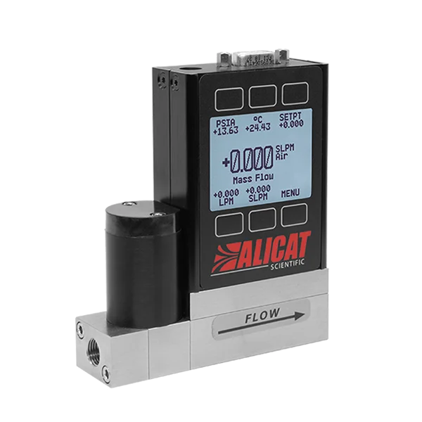
MC-Series Mass Flow Controllers
Optic purge, sample carrier, and chamber backfill or pressure
Laminar differential-pressure mass flow controllers for the low, steady flows a measurement tool depends on, across the optic purge, sample carrier, and chamber backfill. The same instrument can control on its own absolute pressure rather than on flow, so on a continuously pumped chamber it holds the chamber pressure without adding a second device.
- Flow repeatability of ±(0.1% of reading + 0.02% of full scale), 2σ, in the mid-flow ranges; ±(0.2% of reading + 0.02% of full scale) in the low and high-flow ranges
- Mass flow, volumetric flow, absolute pressure, and temperature displayed and reported simultaneously from one body
- Controls on flow, or on its own absolute pressure to hold a chamber pressure on a continuously pumped chamber
- Typical warm-up under one second, so the position is measuring at power-up
- Steady-state control range of 0.01 to 100% of full scale
- 98 to 130 preloaded gas calibrations resident on the instrument; change the active gas by direct selection
- Factory calibrated on air, with real-gas properties evaluated at the instrument’s own measured pressure and temperature
- Analog, serial (RS-232 or RS-485, running Alicat’s native ASCII protocol or Modbus RTU), and industrial network options such as EtherCAT and EtherNet/IP
- No mounting orientation sensitivity, and a NIST-traceable calibration certificate with every unit
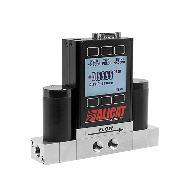
PCD-Series Pressure Controllers
Closed chambers, and pressure held very precisely
For the chamber a flow controller cannot settle: a closed or dead-ended volume where the gas has no natural exhaust, or a pressure that has to be held more tightly than metering flow against the pumps allows. Dual valves admit and vent to hold the setpoint directly, referenced to vacuum.
- Controls absolute pressure referenced to vacuum, with ranges reaching into the Torr region for environmental and variable-pressure chambers
- Dual valves admit and vent, holding a set pressure on a closed or dead-ended chamber without a continuous bleed
- Full-scale range chosen to sit near the chamber’s operating pressure, where vacuum-region accuracy is stated on full scale rather than on reading
- Pressure reported to the tool alongside the conditions each image was taken under
- Analog, serial (RS-232 or RS-485, running Alicat’s native ASCII protocol or Modbus RTU), and industrial network options such as EtherCAT and EtherNet/IP
- NIST-traceable calibration certificate with every unit
Related families for the other positions in the same tool: the MCV-Series vacuum mass flow controllers where a position needs positive isolation as well as control; the Whisper-series low-pressure-drop controllers where purge inlet pressure is constrained; and the MB-Series portable mass flow meters for verifying installed flows in the field or the metrology lab. Talk to an engineer to confirm fit and select a configuration.
Configure the right instruments for your tool’s gas positions.
Send the gas at each position, the flow or pressure it must hold, the inlet pressure available, and the bus your tool controls speak. What comes back is a recommended full scale per position, the pressure drop each will consume, and a build that repeats across a production run.
Outcomes
What holding these positions changes
Instrumenting the positions changes how a drift is diagnosed. When flow, absolute pressure, and temperature are logged behind each measurement from the same body, an unattributed baseline shift stops being a service call and becomes a comparison the tool makes from its own record: the flow held while the supply moved, or the flow moved while the supply did not. A facility problem and an instrument problem read differently in the log, so the first hours of diagnosis no longer go to the optics or the detector by default.
It also changes what the tool carries. One configuration, with an on-board gas library and a control range spanning low optic-purge flow to higher backfill demand, covers the nitrogen, clean dry air, helium, and oxygen positions that would otherwise be four part numbers behaving four different ways. That consolidation pays off across a fleet: the same build repeats across a production run, and the tool holds its stability over its field life.
Value gained
- Drift becomes attributable – flow, absolute pressure, and temperature from a single port let the tool separate a facility problem from an instrument problem in its own logs, not on a service visit.
- Repeatability where it counts – a ±(0.1% of reading + 0.02% of full scale) repeatability term in the mid-flow ranges is the one a tool-level calibration cannot absorb, so it sets run-to-run stability of the purged signal path.
- One platform across positions – an on-board gas library covers nitrogen, clean dry air, helium, and oxygen positions from one configuration, instead of a separate part number per gas.
- Measuring at power-up – typical warm-up under one second keeps startup off the gas control, so the position is measuring as soon as the tool powers up.
- Pressure held to the chamber – a vacuum-referenced dual-valve controller holds Torr-region absolute pressure and reports the condition each image was taken under.
Field deployment notes
Engineering considerations
- Budget the purge inlet pressure before choosing a full scale
- Pressure drop across a laminar element rises with full scale: a standard gas body drops 1.0 PSID at full scale in the 100 to 500 SCCM range and 12.0 PSID at 20 SLPM. A tool fed from a house nitrogen header at low delivered pressure can run out of headroom at the larger full scales, which is the situation the low-pressure-drop variant exists for. The number to check first is available inlet pressure minus the downstream pressure the position has to reach, not the flow. See what pressure drop means for instrument selection.
- A positive-shutoff vacuum position needs actuation air designed into the tool
- The vacuum-service controllers with an integrated positive shutoff valve use a pneumatically actuated valve, which means the tool has to supply and route actuation air to that position. It is a cheap requirement to design in and an expensive one to discover during integration. Confirm the actuation pressure and porting with applications engineering before the panel layout is frozen.
- Orientation freedom is worth using in a dense tool
- The laminar differential-pressure gas bodies are published with no mounting orientation sensitivity, so a position can be mounted vertically, horizontally, or inverted to suit the packaging without a performance penalty or a re-tare procedure tied to attitude. Thermal and float-based instruments in the same tool may not share that freedom, so orientation constraints are worth resolving per position rather than per tool.
Frequently asked questions
Does a mass flow controller in a metrology tool need SEMI qualification?
Not a wafer-process qualification, no. A metrology or inspection tool measures the wafer rather than processing it, so its flow and pressure instruments sit in a measurement or utility position rather than on a recipe-qualified gas stick, and they do not go through the qualified-parts-list process a wafer-recipe controller does, even when the tool inspects production wafers. SEMI is a standards body: it publishes specifications rather than issuing a certification an instrument passes, and conformance is self-declared or third-party assessed. The tool itself is still expected to meet SEMI equipment guidelines such as S2 for safety, but that sits with the tool builder at the equipment level, separate from qualifying the flow instrument for a process. That separation is what keeps the position accessible to a standard instrument line.
Should I specify accuracy or repeatability for a purge position?
Specify repeatability and stability first, then read accuracy as a qualifier. A fixed accuracy offset is absorbed when the tool is characterized and calibrated as built, but a repeatability or drift term moves between runs and power cycles, and nothing in the tool-level calibration is positioned to catch it. Since a purge position’s variation enters the measurement as baseline drift, the repeatability term is what sets the floor.
Our tool platform is standardized on thermal mass flow controllers. What actually changes?
On nitrogen, clean dry air, helium, and oxygen, the measurement accuracy is the same, and modern thermal controllers carry real-gas databases that switch among their stored gases without recalibration. The difference is what each position reports and how the gas set is managed: a laminar differential-pressure instrument derives flow from an absolute pressure and temperature it measures in its own body, so those readings come out as outputs, and its full library sits resident on the instrument and is selected directly, where expanding a thermal’s onboard gas set often means loading models through the manufacturer’s software. Where an established spares pool and fab familiarity matter more than that, staying on thermal is a defensible call.
Can one mass flow controller handle nitrogen, clean dry air, helium, and oxygen?
Yes, on a laminar differential-pressure instrument with an on-board gas library. All four are on the standard gas library of 98 to 130 gases, and the active gas is changed by direct selection, because switching gas switches the property model the instrument evaluates against its own measured pressure and temperature. That is what allows one part number to cover several positions in a tool that runs different gases at each.
How is absolute pressure controlled in a Torr-region measurement chamber?
With a pressure controller referenced to vacuum rather than to the local atmosphere, in a full-scale range chosen to sit near the chamber’s operating pressure. Dual-valve controllers suit closed or dead-ended chambers because they can both admit and vent gas to reach a setpoint without a continuous bleed. Range selection matters because vacuum-region accuracy is commonly specified on full scale rather than on reading.