
Flow and Pressure References for Semiconductor Gas Panel Verification Benches

The reference on a gas panel verification bench
A gas panel, gas stick, or mass flow controller bound for a deposition or etch tool cannot ship until it is verified: every flow channel checked against a known reference, and the assembled box checked for leaks. That work happens on a manufacturing test bench, which needs an instrument it can trust more than the thing it is testing. That instrument is the reference.
The reference occupies a metrology position, not a process one. Panels are verified on nitrogen, clean dry air, or helium, never on the silane, chlorine, or fluorine etch chemistry they will eventually run, so the reference never contacts process gas. It therefore needs no clean, ultra-high-purity, or corrosion-resistant build, and it carries no production qualification, even when the hardware crossing the bench is recipe-tier, because qualification attaches to the process instrument inside the tool rather than to the standard used to check it. A standard instrument line is the correct fit for the position.
A verification bench decides whether a channel passes or fails, and its resolution is the reference’s resolution, because the bench has nothing else to measure against. When a device under test sits near its spec limit, the bench is comparing two numbers that both carry error and has to trust one of them more than the other. A reference no better than the device it judges cannot settle that comparison. So picking the reference looks like a matter of comparing accuracy figures on datasheets, when it depends more on how each figure is written, and on where in the range the bench actually reads it.
Challenge
Why the reference is the hard part of the bench
One verification line covers an enormous range of device full scales. A bench built around a product family may be specified from a few SCCM to several hundred SLPM, about five decades of flow, with the same reference expected to read the bottom of that span as credibly as the top. Integrators commonly require at least 1% of reading across the flow range.
A percent-of-full-scale error term cannot do that, because it stays fixed in absolute terms while the reading falls away from it. Take a reference ranged at 10 SLPM full scale whose accuracy carries a ±0.1% of full-scale term. That term is a flat ±10 SCCM at any reading, which works out to 1% of reading at 1,000 SCCM, 10% at 100 SCCM, and, at a 10 SCCM reading, an uncertainty the size of the reading itself. A device specified that way stays within its published specification the whole way down, but near the bottom of its range it can no longer serve as the reference.
The cost runs both ways. A marginal panel is released because the bench could not separate it from a good one, and the escape surfaces later at the integrator or the tool builder. The opposite error is quieter and usually more expensive: a good panel is held and reworked against a number the bench could never support, with nobody looking for the mistake because nothing appears to have gone wrong.
A reference holds a 1% of reading bar only where its full-scale term has fallen below 1% of the reading. For an accuracy written as the greater of ±0.5% of reading and ±0.1% of full scale, that happens at and above 10% of full scale: a usable band of about 10:1 per device. Size the bench’s reference ladder from that number, not from the device’s turndown figure.
Options
Populating the reference position
Three ways to populate a verification line’s reference position are in current use. Each suits a real bench, and the choice turns on how wide a span of device full scales the line covers and how tight the reading tolerance is.
| Reference arrangement | What it holds at the bottom of the range | Reference instruments carried | When the product mix changes | When to pick it |
|---|---|---|---|---|
| One wide-range reference | The full-scale term dominates as the reading falls, so a device ranged for the top of the line reads the bottom at tens of percent of reading. | One, with one calibration to track and one interface to integrate. | Nothing to re-plumb; the installed range is the range you have. | When the line’s span sits inside a single decade, or the acceptance bar is a coarse functional check rather than a tight reading tolerance. |
| A banded ladder of referencesRecommended | Each device is used only where its full-scale term has fallen below the bar, so every reading is taken in the percent-of-reading regime. | One per band. A four-decade line carries three or four, plus the plumbing to route a channel to the right one. | A new band means adding or re-ranging one device rather than re-specifying the bench. | When one line verifies devices across several decades of full scale against a tight reading tolerance: the ordinary case on a panel builder’s bench. |
| A dedicated reference per channel | The same as a banded ladder for any given channel, since each reference is sized to the channel it serves. | One per channel, so a multi-channel panel bench carries many. | Each reference is fixed to its channel, so a changed mix can strand instruments at ranges the line no longer tests. | When the bench runs one panel design at volume and sequencing time is the constraint, so parallel measurement pays for the extra instruments. |
The banded ladder is the usual answer, and it works on the same arithmetic that sank the single wide-range reference. A percent-of-reading term scales with whatever is being measured, so it stays proportional wherever it is read; a percent-of-full-scale term stays fixed, which is what sets the bottom of a device’s useful band. Banding the range means never reading a device below the point where its full-scale term has grown past the bar.
Wide measurement turndown helps here without being the whole answer. A 10,000:1 measurement range lets one device be read far down its span, so a line needs fewer bands than it otherwise would. Holding a tight reading tolerance across four decades is a separate question, and one device still cannot do it.
Selection
Size the ladder, and run both tests from one family
How the accuracy is written sets the band each device covers, and across the Alicat M-Series that wording changes with the model range. The figures below are the published M-Series specification. Each band runs down to the flow at which the full-scale term falls to 1% of the reading.
| M-Series reference, full scale | Published M-Series mass flow accuracy | Where it holds 1% of reading |
|---|---|---|
| 10 SCCM to 20 SLPM | ±0.5% of reading or ±0.1% of full scale, whichever is greater (high-accuracy option) | At and above 10% of full scale, a band of about 10:1 |
| 50 to 500 SLPM | ±0.4% of reading and ±0.2% of full scale (high-accuracy option) | At and above roughly 33% of full scale, a band of about 3:1 |
| Above 500 SLPM | ±0.8% of reading and ±0.2% of full scale (standard; high-accuracy not offered above 500 SLPM) | Only at full scale; a 1% of reading bar is not held across a band here |
The table shapes the bench design in two ways. Below 20 SLPM the accuracy terms combine as whichever is greater, which is where the 10:1 band comes from. From 50 SLPM up they combine as a sum instead, and the band narrows sharply. Above 500 SLPM the M-Series high-accuracy option is not offered at all, so a 1% of reading bar cannot be held across a range there. A line testing that high either relaxes the bar for its top band or accepts that its high-flow checks happen near full scale.
The other half of the bench: leak and pressure-decay testing
Flow verification is one of two jobs the same bench does. Once a box is assembled it also has to prove leak-tight, checked two ways: that its valves seal when they are closed, and that the assembly holds pressure. A flow-based leak test reads the small flow that gets past a valve that should be shut, which needs a meter ranged low enough for a leak of tens of SCCM to register as a real reading rather than a rounding error. A pressure-decay test brings the assembly to a set pressure, seals it off, and watches the pressure fall over a fixed time on a small internal volume, with a decay budget that can work out to well under 0.1 SCCM equivalent.
A mechanical regulator sets the test pressure. The flow-based leak test reads the leak flow on a low-range meter; the pressure-decay test seals the volume with shutoff valves and reads the pressure over time on an Alicat pressure gauge. Both the leak meter and the decay gauge share the platform and interface of the flow reference, so the whole bench integrates through one interface.
When the device is specified tighter than the bench can resolve at the flow it gets checked at. A tight reading tolerance at a low fraction of full scale can close the margin even in a well-banded ladder. Work the arithmetic at the actual check point before committing the bench design, and where it does not come out, that position calls for a higher-accuracy instrument or a primary flow reference that out-resolves the device, not the working reference the rest of the ladder carries.
When the bench must flow the process chemistry itself. The standard instrument lines are correct here precisely because a verification bench runs inert surrogate gas. A bench running corrosive or toxic process gas is a different facility with different containment, and its instrument selection starts from wetted materials rather than reference accuracy.
These are the standard instrument lines, and they are the correct specification for this position: the reference sees only nitrogen, clean dry air, or helium. Recommendations stay at family level. The full scale of each rung, the accuracy option, the process connection, the connector, and the digital bus are selected with applications engineering against the bench’s own drawing.
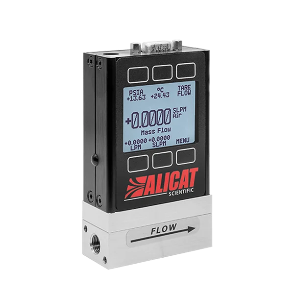
M-Series Mass Flow Meters
Flow-verification reference and low-range leak-flow meter
The reference position on the bench, and at a low full scale the same family reads the leak flow for the flow-based leak test. The model range runs from single-digit SCCM to thousands of SLPM, so the whole ladder comes from one family with one interface and one calibration pedigree.
- ±0.5% of reading or ±0.1% of full scale, whichever is greater, in the high-accuracy option on 10 SCCM to 20 SLPM models
- Flow repeatability of ±(0.1% of reading + 0.02% of full scale) at 2σ on 10 SCCM to 20 SLPM models, which is what separates a marginal device from bench scatter
- Mass flow, volumetric flow, absolute pressure, and gas temperature on one display and one digital reading
- Gas Select™ stores 98 gases, each a real-gas property model, so one reference serves a bench testing panels bound for many gases
- 1.0 PSID pressure drop at full scale on 10 SCCM to 20 SLPM models, which sets how much the reference loads the channel it measures
- Analog; serial (RS-232 or RS-485, running Alicat’s native ASCII protocol or Modbus RTU); and industrial network options such as EtherCAT, EtherNet/IP, and PROFINET; face-seal process connections such as VCR, all configured to the bench’s fixed design
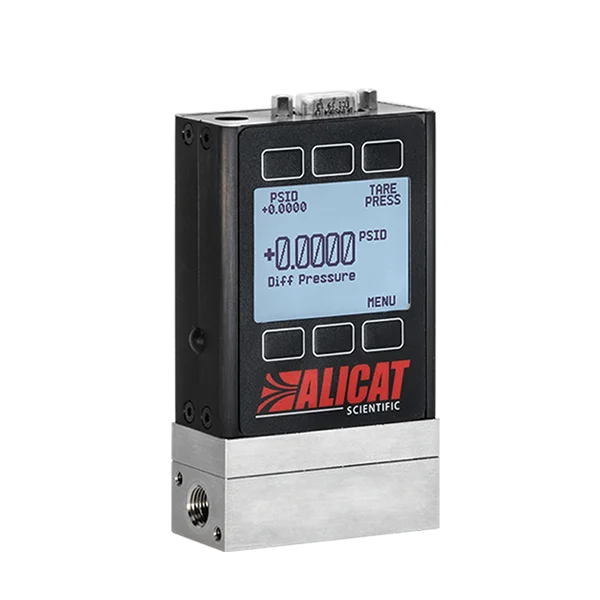
P-Series Pressure Gauges
Pressure readout for the decay test
Reads the pressure over time on the sealed volume for the pressure-decay leak test. It shares the platform, connectors, and digital buses of the flow reference, so it drops onto the same bench and the same bus.
- ±0.125% of full scale pressure accuracy in the high-accuracy option, ±0.25% standard
- Pressure repeatability of ±0.08% of full scale at 2σ, which is what a decay measurement watches as the pressure falls
- 0.07 to 3000 PSI full scales in absolute, gauge, or differential models
- Reads and displays pressure directly, with no separate transducer and readout to integrate
- The same interface as the flow reference: analog; serial (RS-232 or RS-485, running Alicat’s native ASCII protocol or Modbus RTU); and industrial network options such as EtherCAT and EtherNet/IP
Benches that need to set a flow rather than measure one use a controller family such as the MC-Series, in the same footprint and interface as the reference meters. Benches running many simple pneumatic leak-detection channels at low cost can use a compact low-cost meter for that role, kept separate from the reference position. Talk to an engineer to size the ladder and confirm fit.
Size the reference ladder for your verification line.
Send the span of device full scales the line covers, the reading tolerance you hold devices to, the test pressures and any vacuum condition, and your bench’s fixed connection and bus. Back comes a banded ladder with the flow at which each rung holds your bar, the low-range meter and pressure gauge for the leak and decay checks, and current lead time for populating the bench.
Outcomes
What the right reference changes
Sizing the reference to the flow it reads changes the verdict the bench returns. A channel checked in the percent-of-reading regime is separated from its spec limit by a margin the bench can actually support, so a marginal panel is caught and a good one is not reworked against a number that was never real.
It also changes what the bench is built from. When the reference ladder, the low-range leak meter, and the decay pressure gauge all come from one platform, a replicated production bench carries one interface, one calibration pedigree, and one integration to repeat across every copy of the bench. Because the reference reads absolute pressure alongside flow, it records the pressure each channel was verified at, so every result carries the condition it was measured at.
Value gained
- Verdicts the measurement supports – each channel read in the percent-of-reading regime, so a marginal panel is caught and a good one is not held against a number the bench cannot resolve.
- A ladder sized to the line – one reference per band across the span one line tests, from a few SCCM to thousands of SLPM, instead of one meter asked to read every decade.
- Both tests from one platform – reference meters for flow verification, a low-range meter for the flow-based leak test, and a pressure gauge for the decay test, all sharing one interface.
- The standard instrument, correctly – the reference sees only inert surrogate gas, so no clean, UHP, or corrosion-resistant build, and no SEMI qualification, is needed for the position.
- The result anchored to its condition – flow, absolute pressure, and gas temperature from one body record the pressure each channel was verified at.
Bench deployment notes
Engineering considerations
- An analog reading costs uncertainty the digital reading does not
- Alicat specifies an additional ±0.1% of full scale uncertainty on the analog output. On a reference deliberately banded so its full-scale term stays under 1% of reading, adding another full-scale term through a 0 to 5 Vdc or 4 to 20 mA path can undo the banding at the bottom of the band. Where the bar is tight, take the reference reading over the digital bus and leave analog for interlocks and monitoring.
- The reference loads the channel it measures
- An M-Series meter ranged between 10 SCCM and 20 SLPM develops 1.0 PSID at full-scale flow. That pressure appears at the outlet of the device under test, and a device whose behavior depends on outlet condition will read differently on the bench than in service. Either keep the reference’s full-scale pressure drop small against the device’s rated outlet condition, or set the outlet condition deliberately with a back-pressure regulator rather than letting the reference determine it.
- Stated accuracy is after tare, and the zero moves with temperature and pressure
- Alicat flow accuracy is specified after tare, under equilibrium conditions. The published coefficients quantify how far the zero moves as the temperature or pressure leaves the point where the meter was tared: a mass flow zero shift of ±0.01% of full scale per degree Celsius from tare temperature and per atmosphere from tare pressure on 10 SCCM to 20 SLPM models. A meter tared at one condition and then run while the gas temperature or supply pressure changes carries that shift as a full-scale term, at the low readings the banding was meant to protect. Tare at the operating condition, and re-tare when the temperature or pressure moves.
- Every rung of the ladder carries its own calibration schedule
- A reference is only a reference while its calibration is current, and a banded ladder multiplies that obligation across three or four instruments with different ranges and different drift histories. Record which reference and which calibration date was in force for every unit the bench released, so an out-of-tolerance finding on one rung can be bounded to the population that crossed it rather than to everything the line shipped.
- A replicated bench is built to a fixed drawing
- A panel builder runs many identical benches and rebuilds them as product lines change, so the reference has to drop into a fixed footprint, process fitting, connector, and digital bus, and every copy of the bench has to be built the same way. Fixing those on the drawing keeps the fleet consistent, and a build-to-order lead time populates new benches without gating the line.
Frequently asked questions
What accuracy does the reference on a flow verification bench need?
It needs to out-resolve the device under test by a comfortable margin at the flow the device is actually checked at, and integrators commonly set that bar at 1% of reading or better across the range. Accuracy stated as a percent of reading is what holds down the range; a percent-of-full-scale term grows as a share of the reading as the reading falls.
The figure worth checking is the full-scale term underneath the headline number, together with the flow at which that term drops below your bar.
Can one flow meter cover a whole verification bench’s range?
Not to a tight reading tolerance across several decades. Wide measurement turndown lets one meter be read well down its span, which reduces how many instruments a line needs. The percent-of-full-scale term still sets a floor, and below roughly 10% of full scale that floor exceeds 1% of reading.
Real verification lines are populated as a banded ladder, one reference per decade of flow, rather than around a single meter.
Does the reference on a verification bench need to be SEMI qualified?
No. The reference is a metrology position: it checks the customer’s hardware and never enters a process, so it does not go through the qualified-parts-list process a wafer-recipe controller does, even when the panels crossing the bench are recipe-tier. SEMI is a standards body that publishes specifications rather than issuing a certification an instrument passes, and conformance is self-declared.
The bench itself, as a piece of equipment, is still expected to meet the relevant SEMI equipment guidelines such as S2 for safety, but that sits with the bench builder at the equipment level, separate from qualifying the reference.
Does a bench reference need a clean or ultra-high-purity build?
No. A verification bench runs inert surrogate gas, nitrogen most often, with clean dry air and helium for leak and clog checks, so the reference never contacts process chemistry and the standard instrument line is the correct specification. The panels being verified may be destined for corrosive service, but that service happens after they ship.
For the same reason it carries no production qualification: it is a measurement standard, and the qualification belongs to the process instruments it checks.
How is a pressure-decay leak test run on an assembled gas panel?
The assembled box is brought to a defined test pressure, isolated, and the pressure is watched over a fixed time, with an allowed drop over that interval as the pass criterion. Because the internal volume is small and known, the allowed decay converts to an equivalent leak flow, often well under 0.1 SCCM.
A mechanical regulator sets the start pressure and shutoff valves seal the volume, and an Alicat pressure gauge reads the decaying pressure over time. The flow-based leak test uses a low-range flow meter instead; both share the platform and interface of the flow reference.