Types of Gas Flow Meters and Controllers
Knowing the Types of Gas flow meters and controllers is essential for accurately measuring, regulating, and maintaining fluid movement in industrial, laboratory, and research applications. Therefore, these devices play a crucial role in ensuring precise flow rates, stable pressures, and reliable data, optimizing process efficiency and product quality.
Multiple technologies exist for mass and volumetric flow measurement, each suiting different applications. This guide compares key flow measurement methods, helping you choose the right solution based on accuracy, gas type, and environmental conditions.
Laminar Differential Pressure Mass Flow Instruments
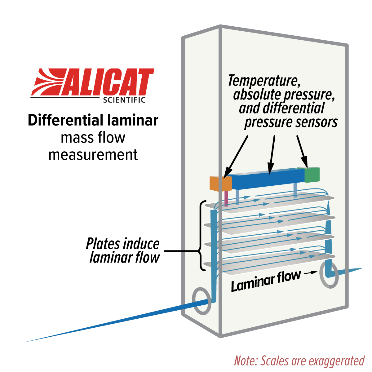
Figure 1. Alicat laminar flow element diagram
Coriolis Mass Flow Instruments
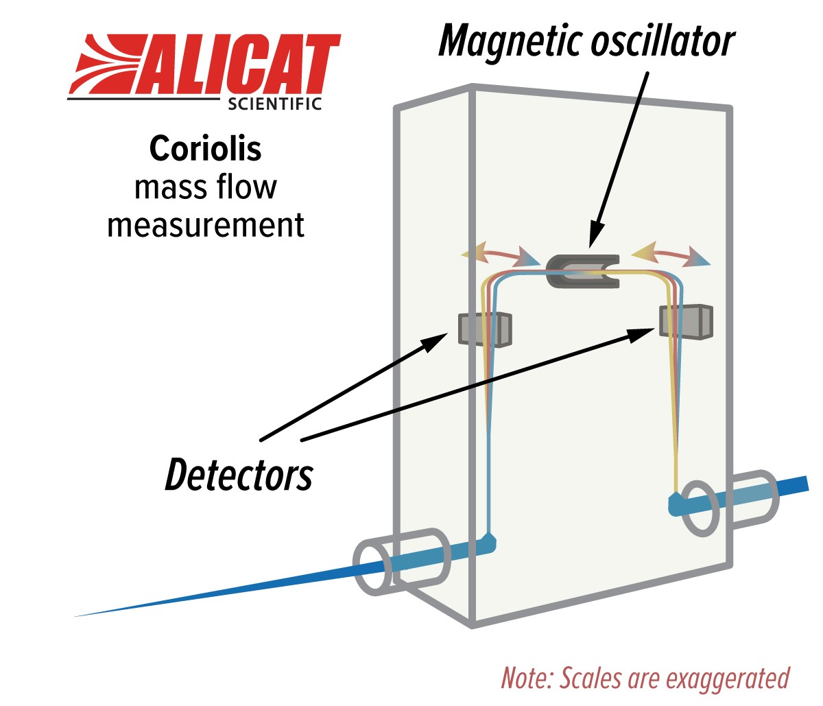
Figure 2. Alicat Coriolis flow element diagram
Thermal Mass Flow Instruments
As the name implies, thermal flow meters and thermal flow controllers use temperature to measure the flow rate of a fluid. Thermal technology traditionally works in one of two ways. Firstly, some meters measure the electrical current required to maintain a constant temperature across a heated element. As fluid flows, it cools the element, dissipating heat. Consequently, higher flow rates necessitate increased current to sustain the element’s temperature, with this current directly proportional to the mass flow rate for a given set of fluid conditions. Fluid conditions are often highly dependent upon temperatures and pressures.
The second method involves measuring temperatures at two points flanking a heated element (hot wire or surface). When fluid passes over this heated element, it transports heat downstream, elevating the downstream sensor’s temperature while reducing the upstream sensor’s temperature. The resultant temperature differential correlates with the fluid’s mass flow rate, subject to the same constraints as the first method.
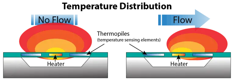
Figure 3. Thermal mass flow meter principle of operation
Ultrasonic Flow Meters
Ultrasonic flow meters use sound waves to measure the flow rate of a fluid. Doppler flow meters transmit ultrasonic sound waves into the fluid. These waves are reflected off particles and bubbles in the fluid. As a result, the frequency change between the transmitted wave and the received wave can be used to measure the velocity of the fluid flow. Time of Flight flow meters use the time differential between transmitted and received sound waves (upstream and downstream) to calculate the velocity of the flow.
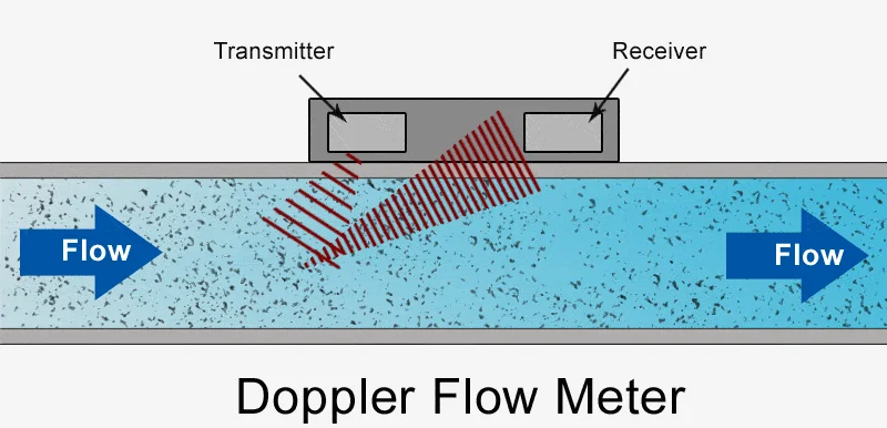
Figure 4. Ultrasonic Doppler flow meter principle of operation
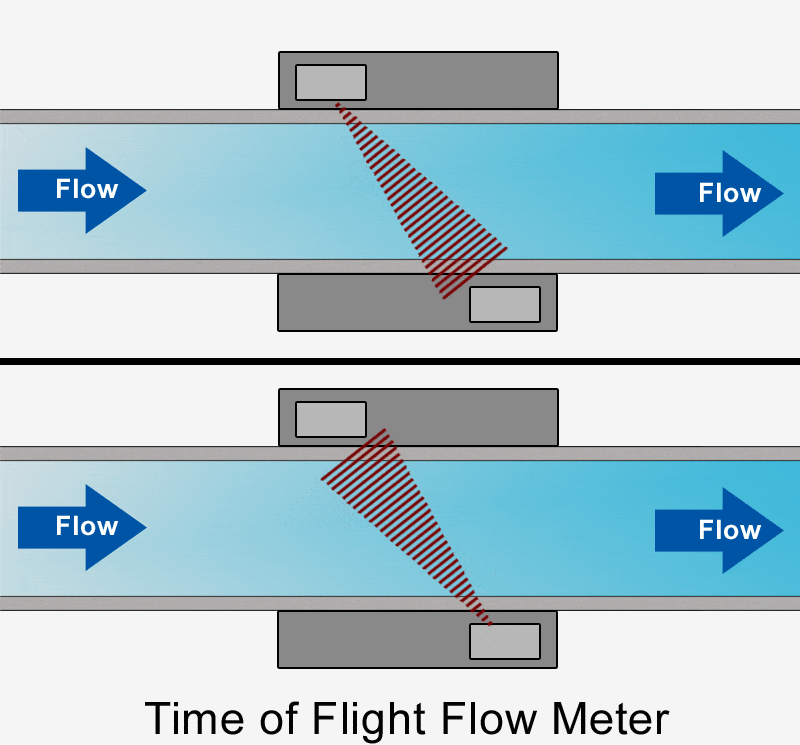
Figure 5. Ultrasonic time-of-flight flow meter principle of operation
Rotameters
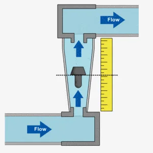
Figure 6. Rotameter principle of operation
Optical Flow Meters
Optical flow meters are used for fluids containing small solid particles that would likely clog devices relying on capillary bypasses or other restrictions to flow. They are also used to measure gas with liquid droplets, or liquid with bubbles.
These meters operate by shining a laser interference pattern into the flow stream, targeting the particles within. When the particles pass through that interference pattern, the reflected light is detected by a photo-receptor. The frequency of the light pulses is proportional to the velocity of the fluid flow.
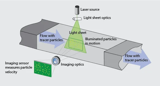
Figure 7. Particle imaging illustration
Venturi Flow Meters
Venturi devices have the advantage of being very low cost, but at the expense of flexibility. The Venturi effect is a reduction in pressure caused by a constriction in a fluid’s flow path.
Pressure sensors measure the pressure before and inside the length of constriction, and the meter calculates fluid velocity using Bernoulli’s Equation. Bernoulli’s principle states that the speed of a fluid is inversely proportional to its pressure. Therefore, by decreasing the pressure of the gas at a known constriction and measuring the differential pressure, the device can determine the volumetric flow rate.

Figure 8. Differential pressure diagram
Gas Flow Technologies Comparison
The following table provides a concise comparison of various gas flow measurement technologies, highlighting their best applications, limitations, and key features. This overview assists in selecting the most suitable instrument for specific operational requirements.
Operating temperature and pressure within sensor limits
Sanitary applications
Corrosive or Aggressive gases
High-pressure
Insertion into pipes
Mixed-phase fluids
Near atmospheric pressure
Multi-phase flows
Unknown compositions
High viscosity gases
Applications with vibrational noise
Unknown compositions
Gases that are dirty, opaque, or coat glass
No warm-up time
No gas property dependency
Low zero shift
Large pipe diameters
Good for mixed-media
Choose the Right Gas Flow Instrument
