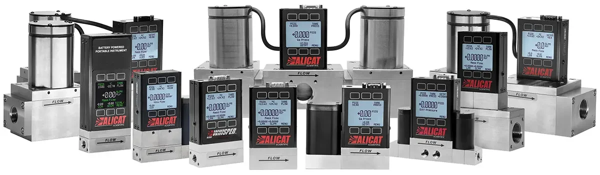
Types of gas flow instruments

There are many ways to measure and control flow. Here we compare common mass and volumetric flow technologies, including Coriolis, laminar differential pressure, thermal, ultrasonic, rotameters, optical, and venturi.

Skip ahead to…

  1. Laminar differential pressure
  2. Coriolis
  3. Thermal
  4. Ultrasonic
  5. Variable area
  6. Optical
  7. Venturi

Laminar differential pressure mass flow instruments

Laminar differential pressure-based (laminar DP) mass flow meters and controllers use the pressure drop created within a laminar flow element (LFE) to measure the mass flow rate of a fluid. To do this, an LFE converts turbulent flow into laminar flow by separating it into an array of thin, parallel channels. The pressure drop across the channel is then measured using a differential pressure sensor.

laminar flow element diagram, showing the operating principle of one type of gas flow meters

Alicat laminar flow element diagram

Because the flow within the channel is in a laminar state, the Poiseuille equation can be used to relate the pressure drop to the volumetric flow rate. The volumetric flow rate can then be converted to a highly accurate, standardized mass flow rate using temperature and pressure dependent density correction factors.

Use cases

Laminar DP flow devices require no warm-up time and are highly accurate due to the precise geometries in their construction. However, any clogging or condensation on the materials will change the geometry and therefore affect the system accuracy. These devices should therefore not be used to flow condensing or dirty gases.

Laminar flow measurement also depends on accurate data for how a gas reacts with varying pressure and temperature, which means knowing the exact gas composition is required for accurate measurement.

Best for
  • Clean, dry gases
  • Operating temperature and pressure within sensor limits
Avoid for
  • Condensing or dirty gases
  • Unknown gas compositions
  • High viscosity gases

Coriolis mass flow instruments

Coriolis mass flow meters and controllers use the Coriolis effect to measure the true mass flow rate of a fluid. The fluid travels through a tube (or set of tubes) which is electromagnetically actuated. As fluid passes through, the moving tube experiences very tiny deflections from its initial vibration pattern.

Sensors measure the magnitude of this deflection, which is entirely dependent on the mass of the fluid. This allows for precise, true mass flow measurements by Coriolis instruments.

Use cases

Coriolis devices provide reliable, high accuracy mass flow measurements even for gases with changing densities. This makes them ideal for applications where gas composition is changing or has unknown physical properties. Because they can be constructed from various materials, Coriolis flow instruments can be also used for sanitary applications and with corrosive, dirty, or aggressive gases.

While Coriolis flow devices tend to have a higher cost of purchase, they require very little maintenance and have lower lifetime costs of ownership than many other flow meters. Some Coriolis devices can even measure multi-phase fluids like slurries, although this is typically only available in higher flow models.

The main drawback of a Coriolis is sensitivity to external vibrations.

Best for
  • Unknown compositions and/or physical properties
  • Sanitary applications
  • Corrosive or aggressive gases
Avoid for
  • Multi-phase fluids
  • Applications with vibrational noise

Thermal flow instruments

As the name implies, thermal flow meters and controllers use heat to measure the flow rate of a fluid. Thermal technology traditionally work in one of two ways. The first type measures the current required to maintain a fixed temperature across a heated element. As the fluid flows, particles contact the element and dissipate or carry away heat.

As the flow rate increases, more current is required to keep the element at a fixed temperature. This current requirement is proportional to the mass flow rate.

Thermal mass flow meter principle of operation

Figure 2. Thermal mass flow meter principle of operation

The second thermal method involves measuring the temperature at two points on either side of an element or ‘hot wire’. As the fluid flows over the element it carries the heat downstream, increasing the temperature of the downstream temperature sensor and reducing the temperature of the upstream sensor. The change in temperature is related to the fluid’s mass flow rate.

Use cases

Thermal flow instruments are calibrated to specific gas properties, and to maintain accuracy are therefore used primarily for pure gases, as well as gases with non-changing, known compositions. The biggest advantage of thermal flow devices is that they can be inserted into large pipes to measure in-line flows of known gases. They can also withstand higher pressures, at the expense of creating a large pressure drop.

Aggressive and coating gases may damage the sensor or necessitate frequent maintenance, especially if contaminated with water.

Best for
  • Gases of known compositions
  • High pressure
  • Insertion into pipes
Avoid for
  • Unknown gas compositions
  • Aggressive gases

Ultrasonic flow meters

Ultrasonic flow meters use sound waves to measure the flow rate of a fluid. Doppler flow meters transmit ultrasonic sound waves into the fluid. These waves are reflected off particles and bubbles in the fluid. The frequency change between the transmitted wave and the received wave can be used to measure the velocity of the fluid flow. Time of Flight flow meters use the frequency change between transmitted and received sound waves to calculate the velocity of a flow.

Ultrasonic Doppler flow meter principle of operation

Figure 3. Ultrasonic Doppler flow meter principle of operation

Ultrasonic time-of-flight flow meter principle of operation

Figure 4. Ultrasonic time-of-flight flow meter principle of operation

Ultrasonic flow meters can be an excellent option if you need to measure flow, but can’t install an invasive, new fixture to your flow path; some meters’ transducers can be strapped or clamped directly to the exterior of a pipe!

The two methods used by ultrasonic flow meters are Doppler and transit time. Both types of meters emit an ultrasonic beam into the fluid medium. Doppler meters measure the change in frequency of the beam caused by the Doppler effect, and use the known speed of sound of the fluid to determine flow. Transit time flow meters emit two beams which reflect back into receiving transducers in the meter. The transmit times of the two beams can be used to find both the average fluid velocity and the speed of sound of the fluid.

Use cases

Ultrasonic flow meters are accurate, repeatable, and function well at extreme pressures and temperatures. Their unique advantage is that they can simply be clamped onto a pipe and offer non-invasive flow measurements. The meter therefore has no wetted parts and can be used when the pipes cannot be interfered with – although this does lower measurement accuracy.

Furthermore since ultrasonic flow meters do not actually contact the flows, they can be used for sanitary, corrosive, or aggressive gases. And unlike most of the other meters discussed here, these meters can accurately flow gases with bubbles and eddies.

The primary limitation of these meters is that they can only flow gases that conduct ultrasonic waves. They are also particularly sensitive to process vibrations and they lose accuracy as the pipe diameter changes, such as when buildup accumulates on pipe walls.

Best for
  • Mixed phase fluids
  • Non-invasive flow measurement
Avoid for
  • Gases that do not conduct ultrasonic waves
  • Applications with vibrational noise

Rotameters

Rotameters, also known as variable area flow meters, use a tube and float to measure volumetric flow rate.

Rotameter principle of operation

Figure 5. Rotameter principle of operation

As the fluid flows through the tube, the float rises. Equilibrium will be reached when pressure and the buoyancy of the float counterbalance gravity. The float’s height in the tube is then used to reference a flow rate on a calibrated measurement reference.

Use cases

Rotameters are the lowest-cost gas flow meters on the market, and can be used with a wide variety of gases, including those that may not be clean enough to flow through laminar DP flow meters.

Rotameters come with three primary drawbacks. As they are dependent on gravity, rotameters must be installed vertically and cannot handle upward flows; gas that is visibly dirty, opaque, or coats the glass of the meter can make it difficult to measure the flow visually; and rotameters can only be calibrated to read volumetric flow rate or a mass flow rate at a specific pressure, limiting the pressure range of a device.

Best for
  • Low-cost
  • Near atmospheric pressure
Avoid for
  • Applications with varying pressure
  • Gases that are dirty, opaque, or coat glass

Optical flow meters

Optical flow meters are used for fluids containing small solid particles that would likely clog devices relying on capillary bypasses or other restrictions to flow. They are also used to measure gas with liquid droplets, or liquid with bubbles.

principle of operation for optical gas flow metersOptical flow meters work by shining a laser perpendicular to the flow stream, so it collides with a particle. The light scattered by the particle is picked up by a photodetector, which generates an electric pulse signal. A second laser positioned further downstream of the first laser repeats this process with a second photodetector, and the velocity of the flowing gas is calculated as the distance the particle travelled over time.

Venturi flow meters

Venturi devices have the advantage of being very low cost, but at the expense of flexibility. The Venturi effect is a reduction in pressure caused by a constriction in a fluid’s flow path.

principle of operation for venturi gas flow metersPressure sensors measure the pressure before and inside the length of constriction, and the meter calculates fluid velocity using Bernoulli’s Equation. Bernoulli’s principle states that the speed of a fluid is inversely proportional to its pressure. This means decreasing the pressure of the gas with a known constriction and measuring the differential pressure yields a volumetric flow rate.

Contact an applications engineer about flow control solutions


WordPress Video Lightbox Plugin