Comparing the Environmental Impacts of Single-Use Bioreactors vs. Stainless Steel

Single‑use plastics for consumer products have long been the bane of the environmental movement, with grocery bags and straws as obvious examples. Single‑use plastics in bioprocessing, however, provide significant environmental advantages compared to the stainless steel alternatives. In addition to providing pharmaceutical companies with flexible, scalable solutions, single‑use bioprocessing equipment has proven to be a much more environmentally‑friendly option than reusable stainless steel bioreactors. This holds true for scales ranging from small pilot facilities to 20,000 L bioreactor skids.

In this article, we look at environmental impacts of single use bioreactors vs. their stainless steel counterparts:

  1. Review literature on the environmental impacts of bioprocessing.
  2. Examine wastewater streams as an example of the environmental impact of clean‑in‑place/steam‑in‑place (CIP/SIP).
  3. Discuss process intensification as a means of reducing the overall environmental impact of bioprocessing.

Studies on environmental impacts of bioprocessing

In this section, we will look at two studies that show single‑use bioreactors are significantly more environmentally friendly than stainless steel reactors. Both of these studies make the following assumptions:

  • CIP/SIP between each batch requires a standard amount of energy and supporting equipment
  • Single‑use plastics are being compared to multiuse stainless steel
  • Single‑use components arrive at the pharmaceutical manufacturing site pre‑sterilized by irradiation
  • Single‑use components are disposed of via hazardous waste incineration (some studies assume heat recovery; it is not shown to have a significant impact on the overall energy costs)

Study 1: Stainless steel bioreactors are more harmful to humans and ecosystems

Purpose & design: A 2014 study by GE Healthcare (now Cytiva) and published in BioPharm International looked at the production of monoclonal antibodies to compare single‑use and stainless steel process technologies. The authors split pharmaceutical production into 14 unit operations, plus an additional support unit encompassing all operations required for CIP/SIP. Energy costs were determined based on the assumption that multiuse equipment has a 10‑year lifetime, with 25% of equipment then reused, 67% recycled, and the remaining 8% landfilled.

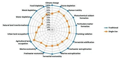
Results & analysis: The authors evaluated the full process trains at 100 L, 500 L, and 2,000 L scales for a 10‑batch campaign. They used 18 categories to assess environmental impact, including human toxicity as well as depletion of water, metal, ozone, and fossil. For 2,000 L volumes, the single‑use bioreactors proved to be advantageous over multiuse bioreactors in each of the 18 categories, as shown in Figure 1.

Comparison of environmental impacts of single-use vs. multi-use bioprocessing. From GE Healthcare Study.

Figure 1. 18 categories were used to assess environmental impacts of single-use vs. multiuse bioprocessing. Impact of multiuse reactors are normalized to 100%. Image from GE Healthcare study.
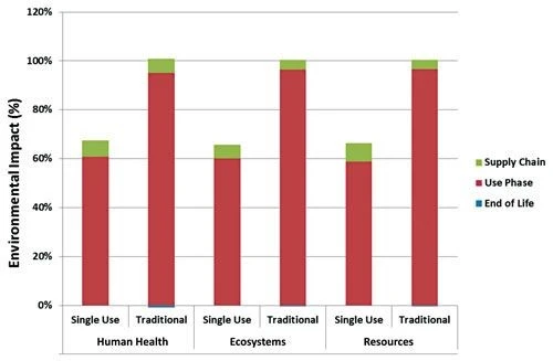
The study compared environmental impact on human health, ecosystems, and resources at various lifecycle phases: supply chain refers to the materials and manufacturing of process equipment (including consumables); use phase refers to the impacts of production, including CIP/SIP; and end‑of‑life refers to the disposal, reuse, or recycling of equipment. Figure 2 shows that about 90% of the environmental impact of a bioprocess results from lifetime usage.
Comparing environmental impacts at various lifecycle stages. Lifetime operation, including CIP/SIP, accounts for 90% of the total environmental cost of bioprocessing. Image from GE Healthcare study.

Figure 2. Comparing environmental impacts at various lifecycle stages. Lifetime operation, including CIP/SIP, accounts for 90% of the total environmental cost of bioprocessing. Image from GE Healthcare study
Key findings: This study concluded that single‑use equipment is significantly more environmentally friendly than traditional stainless steel equipment. The biggest savings are in the energy costs of lifetime usage: with energy savings attributed to removing the processes necessary for CIP/SIP.

Study 2: CIP/SIP accounts for over half of the total energy consumption of stainless steel skids

Purpose & design: In 2009, BioProcess International looked at the energy costs of single‑use vs. multiuse systems. Their energy calculations were based on the following factors:

  • Single‑use plastics are assumed to be made entirely of polypropylene
  • Stainless steel bioreactors have a lifetime of 600 production batches, but the required liquid and air filters must be regularly replaced.
  • Single‑use biocontainers are housed in stainless steel totes without vent filters.
  • Single‑use capsule filters inside stainless steel housings are used instead of standard liquid and exhaust gas filters.
  • Single‑use membrane absorber capsules are used instead of standard chromatography columns and resins.

Results & analysis: Table 1 shows a summary of the energy calculations for single‑use plastic systems compared to multiuse stainless steel. Materials production refers to the energy cost of manufacturing the components for the two solutions; sterilization refers to SIP between batches for stainless steel systems or pre-sterilizing components by irradiation for single‑use systems; and cleaning refers to CIP for reusable skids, most often using a combination of pyrogen‑free distilled water, sodium hydroxide, and phosphoric acid in standard, pre‑determined quantities.

Single-Use Energy Consumption (Megajoules)
Multiuse Stainless Steel Energy Consumption (Megajoules)
Materials Production
4,100
1,100
Sterilization
30
2,000
Cleaning
0
4,900
Total
4,130
8,000
Table 1: Total energy calculations for bioprocessing for single use systems compared to multiuse stainless steel systems. While single-use systems have higher materials costs to regularly replace components, they are significantly less energy intensive over their lifetimes.
While manufacturing stainless steel is significantly more energy intensive than manufacturing plastic, the disposable plastic components must be replaced for each batch. This results in a cumulative energy expenditure to produce single‑use components that is almost 4x greater than the energy expenditure to manufacture the equivalent multiuse components. While single‑use components are often disposed of by incineration, allowing for some energy recovery through heat, there is not nearly enough recovery to overcome the large difference in energy costs.

SIP calculations assumed a steam generator output of 500 kW/h, and 100 L of water necessary to provide 30 minutes of steam at 130oC, with SIP between each batch. In contrast, single‑use components are irradiated by the manufacturer and then disposed of after use. This study found that sterilizing multiuse skids between batches is over 6x more energy intensive than sterilizing single‑use components before use.

The largest energy expenditure in traditional bioreactor systems is in producing the pyrogen‑free distilled water necessary for cleaning. The 4,900 MJ which this study determined to be necessary for cleaning multiuse systems lies in sharp contrast to 0 MJ required for single‑use components, which do not need to be cleaned.

Key findings: Over a lifetime of use, single‑use bioreactors are significantly less energy intensive than multiuse bioreactors. CIP/SIP accounts for the vast majority of the energy requirements for traditional bioreactor skids, meaning the elimination of inline cleaning and sterilization is the key environmental advantage of single‑use systems.

Example: waste streams resulting from CIP/SIP

Waste streams result from cleaning reusable components, and must be processed as they leave pharmaceutical plants before they are introduced into the sewer system. Standard toxicity assessments calculate the concentrations of various trace metals and other materials which may be toxic to organisms, as well as looking at stream volumes, and the expected dilution of the waste streams when mixed with other waste at the treatment plant.

Standard cleaning solutions for reusable stainless steel and plastic components include 1 M sodium hydroxide, 1 M phosphoric acid, pyrogen‑free distilled water, buffers, cleaning agents, and steam. Sanitation solutions are usually diluted bleach, and wipe‑down solutions are generally quaternary disinfectants. These solutions must then all be rinsed several times over — creating chemical runoffs which must be properly handled.

To address the issues associated with chemical waste streams, regulatory drivers have moved pharmaceutical facilities from chemical sanitation to steam sanitation. Steam sanitation creates less chemical runoff and less energy is required to treat the waste streams. However, the energy cost of steam generation can be great enough to offset these advantages.

Impact of CIP/SIP and the role of process intensification as a remedial solution

CIP/SIP has been shown in the studies cited here and others to be the primary contributor to the environmental footprint of a pharmaceutical manufacturing facility. As such, the primary advantage conveyed by single‑use systems is exactly that — they are disposed of and replaced, rather than cleaned and reused. Despite the higher manufacturing costs demanded by components which must be continually replaced, single‑use systems achieve a much lower environmental footprint by avoiding the energy costs of inline cleaning and sterilization.

Despite their environmental advantages, single‑use skids are not always feasible, for reasons ranging from process scale to extreme operating conditions to fluid incompatibilities. Process intensification therefore provides a simple means by which to introduce significant energy savings into the plant.

Hybrid systems provide a practical, environmentally-conscious design

Hybrid systems, consisting of a combination of single‑use and multiuse skids, can offer a unique opportunity to reduce a plant’s environmental footprint without requiring a total overhaul of the manufacturing process. This allows system designers to take advantage of skids with appropriate single‑use solutions, while recognizing their limitations in other areas.

Skids designed for easy CIP/SIP lead to less water and steam, and fewer chemicals

Making more cleanable skids would result in CIP/SIP procedures that require less water and fewer chemicals — resulting in less wastewater treatment, less steam generation, and an all‑around lower energy cost of cleaning. Skids allowing for in‑line buffer dilution would allow for smaller buffer holding tanks, resulting in less equipment to clean and sterilize and time savings from not needing to move various pieces around the facility. This in turn can lead to smaller facility sizes, which have lower HVAC costs.

Operator training means producing only the wastes which are strictly necessary

Expanding training for operators is a simpler step for leaner processing and achieving process intensification. Overages are built into standard operating procedures, but extra‑cautious operators may want to add an extra rinse. Training operators closely on the SOPs and the reasoning behind each step can prevent unnecessary rinsewater or buffer production — and reduce inventory to only what is strictly necessary. This is particularly useful given that refrigerant gases have a large environmental footprint. Together, these factors indicate that single‑use bioreactors compared to stainless steel are not the only factors in the overall environmental impact of bioprocessing.

Enabling Liquid Hydrogen Fuel Systems in Maritime Innovation

Alicat MCRQ Mass Flow Controllers Support TU Delft Hydro Motion Team’s Hydrogen Boat for the Monaco Energy Boat Challenge

Feb 17, 2021 | Bioreactors & Fermenters

Empowering Discovery on Water

The transition to sustainable energy in the maritime sector demands more than ambition, it requires precision. That is why Alicat Scientific is proud to support the TU Delft Hydro Motion Team as a Bronze Partner in their groundbreaking 2025 campaign: to design, build, test and race Mira, a liquid hydrogen-powered boat at the Monaco Energy Boat Challenge.

Equipping this innovative project with our MCRQ mass flow controllers enables the team to manage hydrogen fuel delivery safely and accurately, helping them prove that liquid hydrogen can power the next generation of clean marine propulsion.

Mira at the official reveal, Hydro Motion Team’s 2025 liquid hydrogen-powered boat.

Figure 1: Mira at the official reveal. Hydro Motion Team’s 2025 liquid hydrogen-powered boat.

The Challenge: Making Hydrogen Work for Maritime Transport

The goal of the TU Delft Hydro Motion Team is as ambitious as it is inspiring: to design, build, test, and race a fully functioning boat powered by liquid hydrogen, all within one year, and to compete at the Monaco Energy Boat Challenge 2025. But beyond the competition itself, the team’s mission reaches further. By proving that a boat can operate successfully on liquid hydrogen, they aim to spark broader innovation across the maritime sector and demonstrate hydrogen’s potential as a clean, scalable alternative to fossil fuels.

This project builds on the team’s past successes with compressed hydrogen, already a proven, zero-emission marine fuel. But as the team pushes for longer range and greater onboard efficiency, storage volume and energy density become the next major challenges. To solve this, the team chose to work with liquid hydrogen. With a volumetric energy density three times higher than compressed hydrogen at 350 bar, liquid hydrogen offers a powerful solution for saving space and extending endurance, key requirements in performance vessels.

But storing and using liquid hydrogen introduces challenges. The fuel must be kept at -253°C, requiring insulated cryogenic tanks. The team addresses this with a custom double-walled, vacuum-insulated carbon-fibber tank system, limiting heat ingress to just 7 watts, equivalent to a small LED bulb. To avoid wasting energy, waste heat from the fuel cell is used to bring hydrogen up to the required ~20°C operating temperature before reaching the fuel cell.

These trade-offs (boil-off rates, tank volume, storage weight, and onboard vaporization) are exactly the kinds of real-world constraints this project is designed to explore. And while Mira is a compact, foiling boat, the broader engineering question remains: could a system like this scale to larger vessels, such as ferries? That is the kind of thinking Alicat is excited to support with partners who are pushing the boundaries of what is possible.

The Role of Alicat: Flow Control After Vaporization

In Mira’s hydrogen system, hydrogen is stored as a cryogenic liquid. Before reaching the fuel cell, it passes through a vaporizer, transitioning into gas at ambient temperature. This phase is critical: delivering gas at the right pressure and flow requires stable regulation, fast feedback, and precise control.

Simplified diagram of the Hydro Motion Team’s hydrogen system.

Figure 2: Simplified diagram of the Hydro Motion Team’s hydrogen system.

To meet this need, the team integrated the Alicat MCRQ mass flow controller immediately downstream of the vaporizer. This device manages the mass flow of hydrogen gas into the fuel cell and enables:

  • Delivers stable and precise feed pressure to the fuel cell.
  • Measures hydrogen consumption through real-time mass flow monitoring
  • Monitors pressure and temperature to help prevent fuel cell issues like dehydration or fuel starvation.
  • Supports test validation and real-world performance optimization.

Compact, ATEX Zone 2 certified, and designed for fast system response, the MCRQ integrates easily into the tight constraints of a race-ready vessel. Its role is vital during system development, helping the team collect data, tune parameters, and prepare for race-day performance. In short, it helps translate bold hydrogen engineering into operational reliability.

Alicat’s MCRQ unit mounted inside the Hydro Motion Team’s hydrogen control system.

Figure 3:  Alicat’s MCRQ unit mounted inside the Hydro Motion Team’s hydrogen control system.

Why the MCRQ Was Selected

The Hydro Motion Team, together with our application engineers, selected the Alicat MCRQ series for its proven capability in low-flow hydrogen gas applications, offering a powerful combination of precision, speed, and safety. Key features that influenced the decision include:

  • Flow range of 0–1.5 g/s, which translates to ±0.01 g/s uncertainty at a nominal 1 g/s flow, small enough to maintain consistent fuel cell output.
  • 4–20 mA analog output, chosen specifically for its high-speed update rates (kHz range)
  • ATEX Zone 2 IIC certification, requiring minimal additional safety infrastructure.
  • Upstream valve position, enabling precise regulation of downstream feed pressure, supporting target values like the ~2.5 bar commonly seen in fuel cell stacks.
  • ±1.0% accuracy of reading (or ±0.2% of full scale)

Together, these features provide the team with a robust, compact, and responsive solution, a key enabler of real-world testing and a step toward scalable, clean hydrogen propulsion.

Competition Progress and What Comes Next

The TU Delft team unveiled the boat, Mira, earlier this year and is now deep into the testing phase, preparing for the Monaco Energy Boat Challenge 2025.

As testing progresses, the team continues optimizing the integration between hydrogen storage, vaporization, and control systems. Alicat’s instrumentation plays a central role in capturing this performance data for analysis and refinement.

This partnership represents more than a technical contribution. It reflects our belief that sustainable innovation thrives where education, engineering, and real-world experimentation meet.

By supporting the Hydro Motion Team and their work on Mira, Alicat contributes to:

  • Advancing liquid hydrogen fuel systems in marine transport
  • Empowering hands-on engineering education
  • Promoting practical low-emission propulsion technologies

We are honoured to be part of this project and proud to know that our instruments are helping to steer the future of clean maritime energy.

Together, we are not just measuring hydrogen. We are helping to Fuel the Future.

Your Title Goes Here

Alicat Newsletter

Sign-up for our newsletter to be informed of product applications, updates, news, and upcoming events

Related articles

Closed Loop Outgassed Materials

Measuring outgassed material in the bioreactor headspace is a powerful tool for understanding the metabolic activity of your cell culture and the effectiveness of your...

read more